


13-74
BE1-CDS240 Testing and Maintenance
9365200990 Rev F
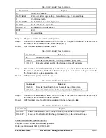
Command
Purpose
EXIT
Exit.
Y Save
settings.
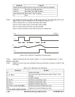
Step 12: Verify the BF time delay by applying nominal current for the duration given in the following
steps:
1. Apply
nominal
current to phase A for 4 cycles (67 ms at 60 Hz). No trip should occur.
2. Apply nominal current to phase A for 5 cycles. (83 ms at 60 Hz). No trip should occur.
3. Apply nominal current to phase A for 7 cycles (117 ms at 60 Hz). A BF trip should occur.
Use the RS-LGC command to retrieve an SER report and verify that a BF trip was logged
100 milliseconds ±0.5 percent or
½ cycles; whichever is greater plus 2¼ cycles
maximum for currents
≥
5 times the pickup setting. Three cycles maximum for a current
of 1.5 times pickup. Four cycles maximum for a current of 1.05 times the pickup setting.
Step 13: (Optional.) Raise 50TP pickup setting to 10 amps and apply nominal current to the relay. Note
that OUT1 and 2 do not operate. No initiate prevents operation of the breaker failure function,
blocking the breaker fail logic.
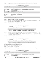
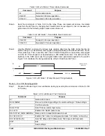
Step 14: Verify Control Time function by first transmitting the settings in Table 13-81.
Table 13-81. Control Time Delay Commands
Command
Purpose
A=
Gain write access
S0-50TP=2.0,0
Set pickup at 2 amps, 0ms time delay
S0-50BF=100m,1.0,1.0,200m
Set Control Timer= 0 ms, PFD = 1amp & GFD = 1amp, BF time delay
at 200 ms
EXIT
Exit
Y Save
settings
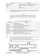
Step 15: Connect a current source to terminals A3* and A4 (A-phase input Current Circuit 1). Apply
nominal current to the relay and note operation of OUT3 and no operation of OUT1 and 2. To
verify control time, apply nominal current and start the test set timer. Use OUT3 to stop the
timer. Timer Accuracy = ±0.5% or
½ cycles; whichever is greater.
Step 16: (Optional.) Repeat Steps 3 through 9 for the phase B and phase C elements.
Step 17: Repeat Steps 1 through 10 for the 150BF, 250BF, and 350BF elements.
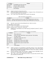
Virtual Switch Verification (43/143/243/343/443/543/643/743)
To test the virtual switches, we verify each mode of operation but do not verify each of the eight virtual
switches. In your testing, you may substitute any or all of the switches as you choose. If you give an
invalid command such as CS-243=1/CO-243=1 when Switch 243 is programmed for Mode 3 operation,
the relay will not operate on the command and if you were using the ASCII command interface, the
monitor would return an
INVALID PARAMETER
. For more information on virtual switch operation, see
Section 4,
Protection and Control Functions, Virtual Switches.
You may verify operation of virtual switches
by monitoring the programmed output contacts, by monitoring the front panel interface Screen \CTRL\xx
or by using the RS-LGC command to retrieve logic variable data from the SER. You may also use the
RG-STAT command. See Section 6,
Reporting and Alarm Functions,
for more information on reports.
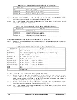
Virtual Switch Mode 1 Operation (On/Off/Pulse)
Purpose
: To verify virtual switch Mode 1 operation.
Reference Commands:
SL-43, CS/CO-43.
Step 1:
Prepare for Mode 1 testing by transmitting the commands in Table 13-82 to the relay.
Summary of Contents for BE1-CDS240
Page 2: ......
Page 8: ...vi BE1 CDS240 Introduction 9365200990 Rev F This page intentionally left blank ...
Page 38: ...1 28 BE1 CDS240 General Information 9365200990 Rev F This page intentionally left blank ...
Page 40: ...ii BE1 CDS240 Quick Start 9365200990 Rev F This page intentionally left blank ...
Page 152: ...ii BE1 CDS240 Metering 9365200990 Rev F This page intentionally left blank ...
Page 226: ...iv BE1 CDS240 Application 9365200990 Rev F This page intentionally left blank ...
Page 286: ...ii BE1 CDS240 Security 9365200990 Rev F This page intentionally left blank ...
Page 290: ...9 4 BE1 CDS240 Security 9365200990 Rev F This page intentionally left blank ...
Page 292: ...ii BE1 CDS240 Human Machine Interface 9365200990 Rev F This page intentionally left blank ...
Page 306: ...10 14 BE1 CDS240 Human Machine Interface 9365200990 Rev F This page intentionally left blank ...
Page 308: ...ii BE1 CDS240 ASCII Command Interface 9365200990 Rev F This page intentionally left blank ...
Page 342: ...11 34 BE1 CDS240 ASCII Command Interface 9365200990 Rev F This page intentionally left blank ...
Page 349: ...Figure 12 5 Horizontal Rack Mount Front View 9365200990 Rev F BE1 CDS240 Installation 12 5 ...
Page 361: ...Figure 12 17 Typical DC Connection Diagrams 9365200990 Rev F BE1 CDS240 Installation 12 17 ...
Page 372: ...12 28 BE1 CDS240 Installation 9365200990 Rev F This page intentionally left blank ...
Page 468: ...13 92 BE1 CDS240 Testing and Maintenance 9365200990 Rev F This page intentionally left blank ...
Page 512: ...14 42 BE1 CDS240 BESTCOMS Software 9365200990 Rev F This page intentionally left blank ...
Page 544: ...ii BE1 CDS240 Terminal Communication 9365200990 Rev F This page intentionally left blank ...
Page 550: ...ii BE1 CDS240 Settings Calculations 9365200990 Rev F This page intentionally left blank ...
Page 578: ...D 28 BE1 CDS240 Settings Calculations 9365200990 Rev F This page intentionally left blank ...
Page 579: ......


