


13-76
BE1-CDS240 Testing and Maintenance
9365200990 Rev F
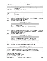
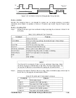
Step 1:
Prepare for Mode 2 testing by transmitting the commands in Table 13-86 to the relay.
Table 13-86. Mode 2 Test Commands
Command
Purpose
A=
Gains write access.
SL-N=NONE
Zero out custom logic settings. Overwrite with logic = None settings.
Y
Confirm overwrite.
SL-N=MODE2
Sets MODE2 as custom logic name.
SL-143=2
Sets 143 to Mode 2 operation.
SL-VO1=143
Enables OUT1 to close for 143.
EXIT
Exit.
Y Save
settings.
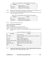
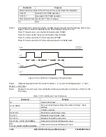
Step 2:
Prepare to monitor the virtual switch operation.
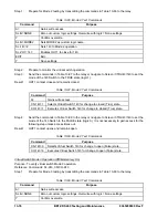
Step 3:
Send the commands in Table 13-87 to the relay or navigate to Screen \CTRL\43\143 to set the
mode of the 143 Switch to the TRUE state (logic 1).
Result: OUT1 contact closes and remains closed.
Table 13-87. Mode 2 Test Commands
Command
Purpose
A=
Gains write access.
CS-143=1
Selects Virtual Switch 143 for change to closed (True) state.
CO-143=1
Executes Virtual Switch 143 for change to closed (True) state.
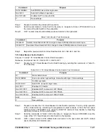
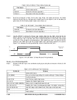
Step 4:
Send the commands in Table 13-88 to the relay or navigate to Screen \CTRL\43\143 to set the
mode of the 143 Switch to the FALSE state (logic 0). It is not necessary to gain access for the
following step unless access times out.
Result: OUT1 contact opens and remains open.
Table 13-88. Mode 2 Test Commands
Command
Purpose
CS-143=0
Selects Virtual Switch 143 for change to open (False) state.
CO-143=0
Executes Virtual Switch 143 for change to open (False) state.
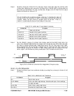
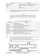
Virtual Switch Mode 3 Operation (Off/Momentary On)
Purpose
: To verify virtual switch Mode 3 operation.
Reference Commands:
SL-243, CS/CO-243
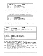
Step 1:
Prepare for Mode 3 testing by transmitting the commands in Table 13-89 to the relay.
Table 13-89. Mode 3 Test Commands
Command
Purpose
A=
Gains write access.
SL-N=NONE
Zero out custom logic settings. Overwrite with logic = None settings.
Y
Confirm overwrite.
Summary of Contents for BE1-CDS240
Page 2: ......
Page 8: ...vi BE1 CDS240 Introduction 9365200990 Rev F This page intentionally left blank ...
Page 38: ...1 28 BE1 CDS240 General Information 9365200990 Rev F This page intentionally left blank ...
Page 40: ...ii BE1 CDS240 Quick Start 9365200990 Rev F This page intentionally left blank ...
Page 152: ...ii BE1 CDS240 Metering 9365200990 Rev F This page intentionally left blank ...
Page 226: ...iv BE1 CDS240 Application 9365200990 Rev F This page intentionally left blank ...
Page 286: ...ii BE1 CDS240 Security 9365200990 Rev F This page intentionally left blank ...
Page 290: ...9 4 BE1 CDS240 Security 9365200990 Rev F This page intentionally left blank ...
Page 292: ...ii BE1 CDS240 Human Machine Interface 9365200990 Rev F This page intentionally left blank ...
Page 306: ...10 14 BE1 CDS240 Human Machine Interface 9365200990 Rev F This page intentionally left blank ...
Page 308: ...ii BE1 CDS240 ASCII Command Interface 9365200990 Rev F This page intentionally left blank ...
Page 342: ...11 34 BE1 CDS240 ASCII Command Interface 9365200990 Rev F This page intentionally left blank ...
Page 349: ...Figure 12 5 Horizontal Rack Mount Front View 9365200990 Rev F BE1 CDS240 Installation 12 5 ...
Page 361: ...Figure 12 17 Typical DC Connection Diagrams 9365200990 Rev F BE1 CDS240 Installation 12 17 ...
Page 372: ...12 28 BE1 CDS240 Installation 9365200990 Rev F This page intentionally left blank ...
Page 468: ...13 92 BE1 CDS240 Testing and Maintenance 9365200990 Rev F This page intentionally left blank ...
Page 512: ...14 42 BE1 CDS240 BESTCOMS Software 9365200990 Rev F This page intentionally left blank ...
Page 544: ...ii BE1 CDS240 Terminal Communication 9365200990 Rev F This page intentionally left blank ...
Page 550: ...ii BE1 CDS240 Settings Calculations 9365200990 Rev F This page intentionally left blank ...
Page 578: ...D 28 BE1 CDS240 Settings Calculations 9365200990 Rev F This page intentionally left blank ...
Page 579: ......