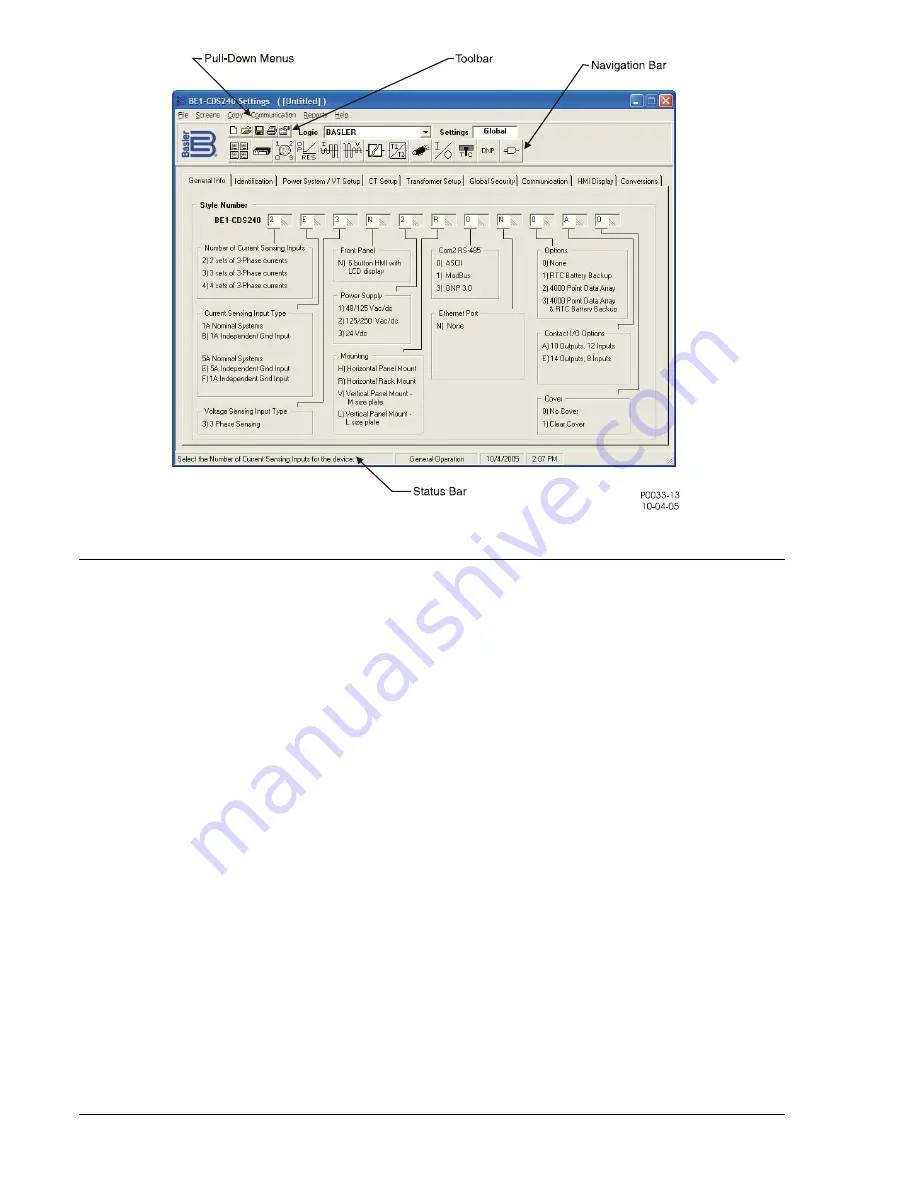
Figure 14-1. Typical User Interface Components
INSTALLATION
BESTCOMS for BE1-CDS240 software contains a setup utility that installs the program on your PC. (This
is typical for all of the BE1 numerical systems.) When it installs the program, an uninstall icon (in the
Control Panel, Add/Remove Programs feature) is created that you may use to uninstall (remove) the
program from your PC. The minimum recommended operating requirements are listed in the following
paragraph.
PC Requirements
486DX2-100-MHz or higher processor
20 megabytes (MB) of RAM
Microsoft
Windows
2000/XP/Vista
7 MB of hard disk space
CD-ROM drive for installation
One available serial port
Installing the Program on Your PC Using Microsoft
Windows
1. Insert the CD in the PC CD-ROM drive.
2. When
the
Setup and Documentation CD
menu appears, click the install button for the
BESTCOMS PC Program. The setup utility automatically installs “BESTCOMS for BE1-CDS240”
on your PC.
When BESTCOMS installation is complete, a Basler Electric folder is added to the Windows
program menu. This folder is accessed by clicking the Start button and Programs and then Basler
Electric. The
Basler Electric
folder contains an icon for the “BESTCOMS for BE1-CDS240” program.
Connecting the PC to the Relay
Remember, you do not have to have a unit connected to the PC to operate BESTCOMS and program
settings. If you have an actual unit, connect a communication cable between the front RS-232
communication port on the BE1-CDS240 front panel and an appropriate communication port on the PC.
14-2
BE1-CDS240 BESTCOMS Software
9365200990 Rev F
Summary of Contents for BE1-CDS240
Page 2: ......
Page 8: ...vi BE1 CDS240 Introduction 9365200990 Rev F This page intentionally left blank ...
Page 38: ...1 28 BE1 CDS240 General Information 9365200990 Rev F This page intentionally left blank ...
Page 40: ...ii BE1 CDS240 Quick Start 9365200990 Rev F This page intentionally left blank ...
Page 152: ...ii BE1 CDS240 Metering 9365200990 Rev F This page intentionally left blank ...
Page 226: ...iv BE1 CDS240 Application 9365200990 Rev F This page intentionally left blank ...
Page 286: ...ii BE1 CDS240 Security 9365200990 Rev F This page intentionally left blank ...
Page 290: ...9 4 BE1 CDS240 Security 9365200990 Rev F This page intentionally left blank ...
Page 292: ...ii BE1 CDS240 Human Machine Interface 9365200990 Rev F This page intentionally left blank ...
Page 306: ...10 14 BE1 CDS240 Human Machine Interface 9365200990 Rev F This page intentionally left blank ...
Page 308: ...ii BE1 CDS240 ASCII Command Interface 9365200990 Rev F This page intentionally left blank ...
Page 342: ...11 34 BE1 CDS240 ASCII Command Interface 9365200990 Rev F This page intentionally left blank ...
Page 349: ...Figure 12 5 Horizontal Rack Mount Front View 9365200990 Rev F BE1 CDS240 Installation 12 5 ...
Page 361: ...Figure 12 17 Typical DC Connection Diagrams 9365200990 Rev F BE1 CDS240 Installation 12 17 ...
Page 372: ...12 28 BE1 CDS240 Installation 9365200990 Rev F This page intentionally left blank ...
Page 468: ...13 92 BE1 CDS240 Testing and Maintenance 9365200990 Rev F This page intentionally left blank ...
Page 512: ...14 42 BE1 CDS240 BESTCOMS Software 9365200990 Rev F This page intentionally left blank ...
Page 544: ...ii BE1 CDS240 Terminal Communication 9365200990 Rev F This page intentionally left blank ...
Page 550: ...ii BE1 CDS240 Settings Calculations 9365200990 Rev F This page intentionally left blank ...
Page 578: ...D 28 BE1 CDS240 Settings Calculations 9365200990 Rev F This page intentionally left blank ...
Page 579: ......


