Inputs and Outputs
Pull down the
Screens
menu and select
Inputs and Outputs
or click on the Inputs and Outputs
icon that is shown at the right margin of this paragraph. This screen has three folder tabs and the
first tab is
Inputs 1 - 6.
Inputs 1 - 6
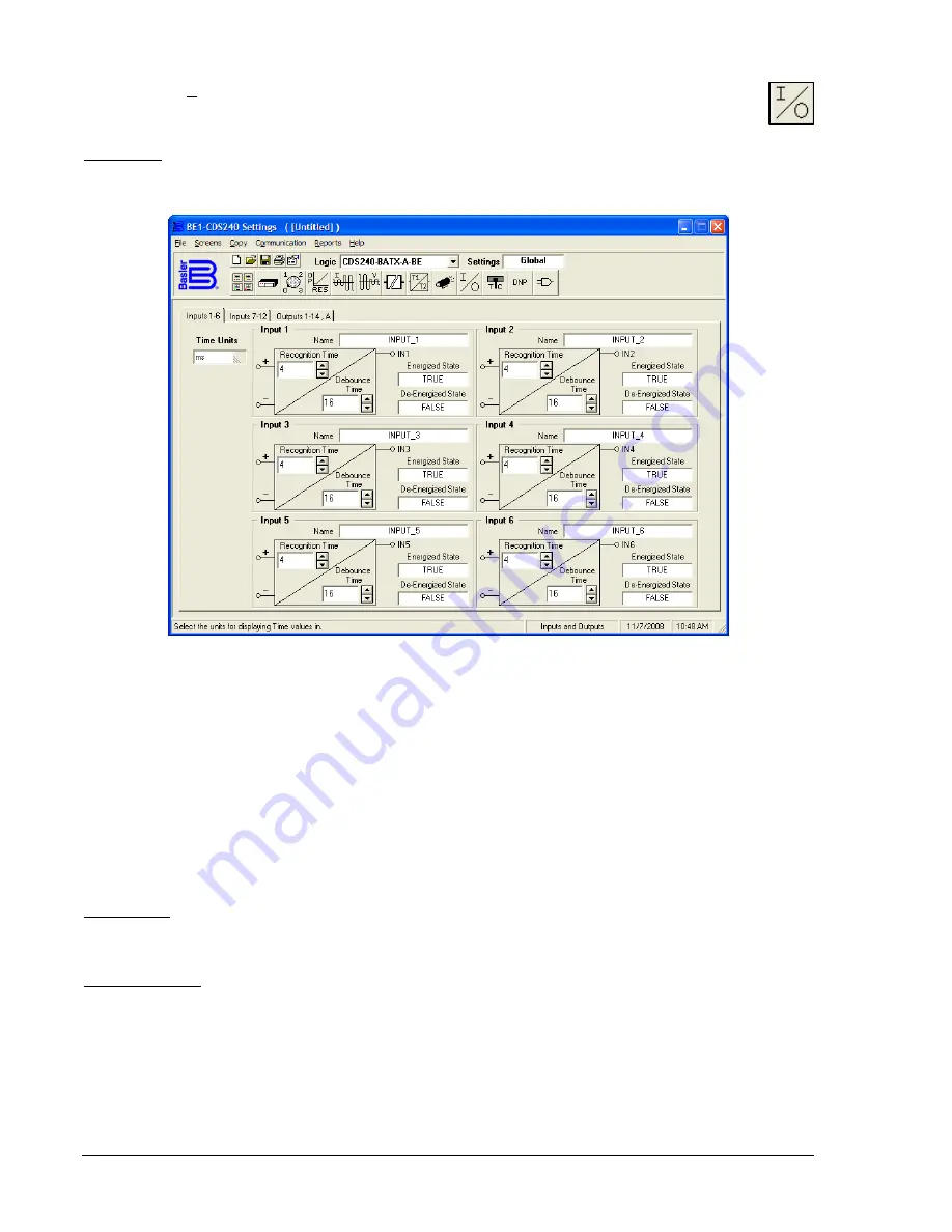
Six programmable inputs in the BE1-CDS240 relay are set by this tab. See Figure 14-38.
Figure 14-38. Inputs and Outputs Screen, Inputs 1 - 6 Tab
To program how long the Input 1 contact must be closed for it to be recognized as closed, first pull down
the
Time Units
menu and set the units for the appropriate time measurement (i.e., ms (default), seconds
minutes, or cycles). Then, click on the
Input 1, Recognition Time
and enter the new value or use the
appropriate (
Up
or
Down
) arrow buttons to set the new value. To program how long the Input 1 contact
must be open to be recognized as open, click on the
Input 1, Debounce Time
and enter the new value or
use the appropriate (
Up
or
Down
) arrow buttons to set the new value.
You can assign a meaningful name to each input. This makes sequential events reports easier to
analyze. To assign a meaningful name to Input 1, click in the
Name
field and enter the new name. To
change the label for the
Energized State
, click on the
Energized State
field and enter the new name. To
change the label for the
De-Energized State
, click on the
De-Energized State
field and enter the new
name. The remaining five inputs have the same functions.
Inputs 7 - 12
There are six programmable inputs in the BE1-CDS240 relay that are set by this tab. Functionality is the
same as described for Inputs 1 - 6.
Outputs 1 - 14, A
On this tab (Figure 14-39), the only feature that you may change is to select the programmable hold
attribute. To select the hold attribute (contacts remain closed for 200 milliseconds) for any output, click on
the
Hold Attribute
field for that output. To change the label for any of the virtual outputs, see the
paragraphs on
BESTlogic, Virtual Outputs,
later in this section.
14-28
BE1-CDS240 BESTCOMS Software
9365200990 Rev F
Summary of Contents for BE1-CDS240
Page 2: ......
Page 8: ...vi BE1 CDS240 Introduction 9365200990 Rev F This page intentionally left blank ...
Page 38: ...1 28 BE1 CDS240 General Information 9365200990 Rev F This page intentionally left blank ...
Page 40: ...ii BE1 CDS240 Quick Start 9365200990 Rev F This page intentionally left blank ...
Page 152: ...ii BE1 CDS240 Metering 9365200990 Rev F This page intentionally left blank ...
Page 226: ...iv BE1 CDS240 Application 9365200990 Rev F This page intentionally left blank ...
Page 286: ...ii BE1 CDS240 Security 9365200990 Rev F This page intentionally left blank ...
Page 290: ...9 4 BE1 CDS240 Security 9365200990 Rev F This page intentionally left blank ...
Page 292: ...ii BE1 CDS240 Human Machine Interface 9365200990 Rev F This page intentionally left blank ...
Page 306: ...10 14 BE1 CDS240 Human Machine Interface 9365200990 Rev F This page intentionally left blank ...
Page 308: ...ii BE1 CDS240 ASCII Command Interface 9365200990 Rev F This page intentionally left blank ...
Page 342: ...11 34 BE1 CDS240 ASCII Command Interface 9365200990 Rev F This page intentionally left blank ...
Page 349: ...Figure 12 5 Horizontal Rack Mount Front View 9365200990 Rev F BE1 CDS240 Installation 12 5 ...
Page 361: ...Figure 12 17 Typical DC Connection Diagrams 9365200990 Rev F BE1 CDS240 Installation 12 17 ...
Page 372: ...12 28 BE1 CDS240 Installation 9365200990 Rev F This page intentionally left blank ...
Page 468: ...13 92 BE1 CDS240 Testing and Maintenance 9365200990 Rev F This page intentionally left blank ...
Page 512: ...14 42 BE1 CDS240 BESTCOMS Software 9365200990 Rev F This page intentionally left blank ...
Page 544: ...ii BE1 CDS240 Terminal Communication 9365200990 Rev F This page intentionally left blank ...
Page 550: ...ii BE1 CDS240 Settings Calculations 9365200990 Rev F This page intentionally left blank ...
Page 578: ...D 28 BE1 CDS240 Settings Calculations 9365200990 Rev F This page intentionally left blank ...
Page 579: ......


