EXAMPLE TWO – TWO WINDING TRANSFORMER
Verify CT Performance
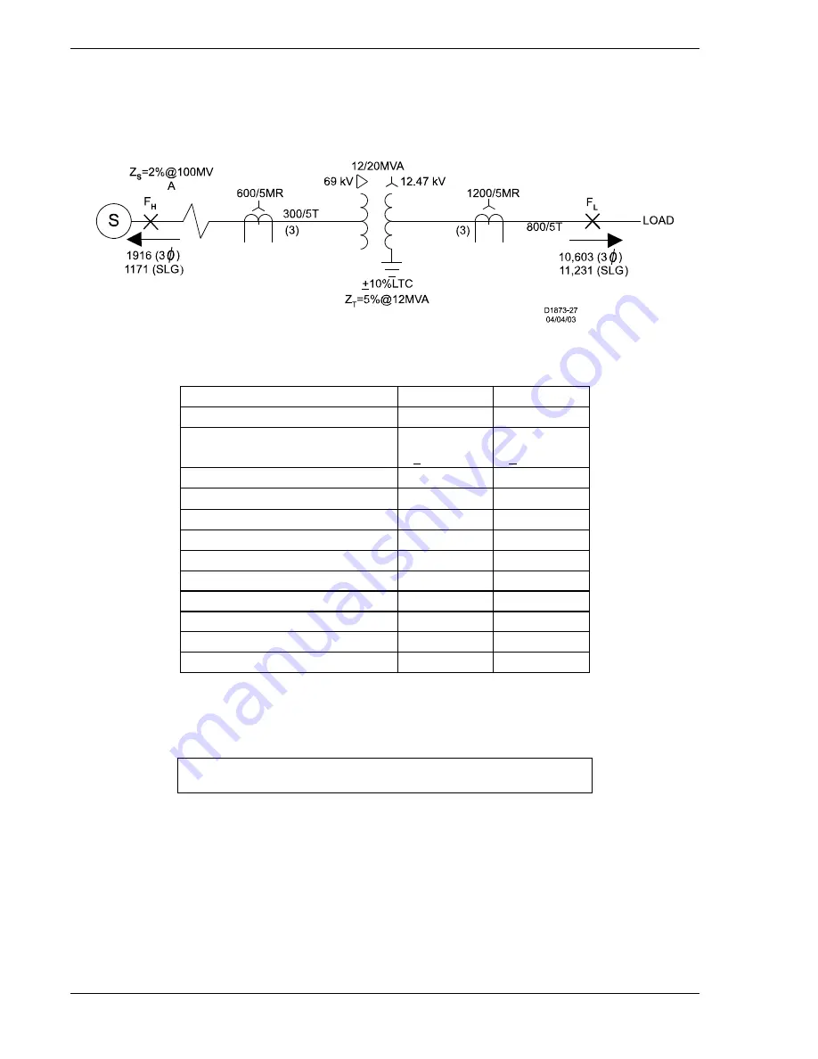
Refer to Figure D-3 and Table D-3 for the application parameters used in this example.
Figure D-3. Two Winding Transformer Relay Setting Calculation Example
Table D-3. Example 2 Specifications
SPECIFICATIONS
HIGH SIDE
LOW SIDE
Nominal Voltage
69 kV
12.47 kV
Taps
70.725 kV
+2.5%, 5%
12.47 Kv
+10% Auto
MVA, SC, FA
12/20
12/20
XFMR connection
Delta Wye
CT connection
Wye
Wye
CT ratio
600:5
1200:5
CT tap
300:5
800:5
CT accuracy class
400
800
One-way lead burden (ohms) †
0.7
0.7
Input #
1
2
Fault current (three-phase)
1,916
10,603
Fault current (single-phase)
1,171
11,231
Standard connection: High voltage leads the low voltage by 30
.
†
L
T
resistance at tap and lead resistance (R
L
+ R
CT
).
NOTE
Please read the discussion at the start of Example 1 calculations.
D-12
BE1-CDS240 Settings Calculations
9365200990 Rev F
Summary of Contents for BE1-CDS240
Page 2: ......
Page 8: ...vi BE1 CDS240 Introduction 9365200990 Rev F This page intentionally left blank ...
Page 38: ...1 28 BE1 CDS240 General Information 9365200990 Rev F This page intentionally left blank ...
Page 40: ...ii BE1 CDS240 Quick Start 9365200990 Rev F This page intentionally left blank ...
Page 152: ...ii BE1 CDS240 Metering 9365200990 Rev F This page intentionally left blank ...
Page 226: ...iv BE1 CDS240 Application 9365200990 Rev F This page intentionally left blank ...
Page 286: ...ii BE1 CDS240 Security 9365200990 Rev F This page intentionally left blank ...
Page 290: ...9 4 BE1 CDS240 Security 9365200990 Rev F This page intentionally left blank ...
Page 292: ...ii BE1 CDS240 Human Machine Interface 9365200990 Rev F This page intentionally left blank ...
Page 306: ...10 14 BE1 CDS240 Human Machine Interface 9365200990 Rev F This page intentionally left blank ...
Page 308: ...ii BE1 CDS240 ASCII Command Interface 9365200990 Rev F This page intentionally left blank ...
Page 342: ...11 34 BE1 CDS240 ASCII Command Interface 9365200990 Rev F This page intentionally left blank ...
Page 349: ...Figure 12 5 Horizontal Rack Mount Front View 9365200990 Rev F BE1 CDS240 Installation 12 5 ...
Page 361: ...Figure 12 17 Typical DC Connection Diagrams 9365200990 Rev F BE1 CDS240 Installation 12 17 ...
Page 372: ...12 28 BE1 CDS240 Installation 9365200990 Rev F This page intentionally left blank ...
Page 468: ...13 92 BE1 CDS240 Testing and Maintenance 9365200990 Rev F This page intentionally left blank ...
Page 512: ...14 42 BE1 CDS240 BESTCOMS Software 9365200990 Rev F This page intentionally left blank ...
Page 544: ...ii BE1 CDS240 Terminal Communication 9365200990 Rev F This page intentionally left blank ...
Page 550: ...ii BE1 CDS240 Settings Calculations 9365200990 Rev F This page intentionally left blank ...
Page 578: ...D 28 BE1 CDS240 Settings Calculations 9365200990 Rev F This page intentionally left blank ...
Page 579: ......


