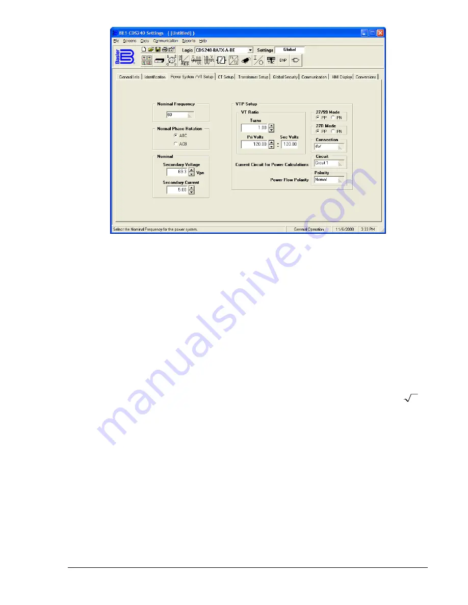
Figure 3-1. General Operation Screen, Power System/VT Setup Tab
Nominal Frequency.
When the voltage and current signals are too low for the frequency to be reliably
measured, the ADC circuit defaults to operation at the nominal frequency setting. This can be set for
operation on either 50 or 60-hertz power systems using BESTCOMS, the optional HMI using Screen
6.3.2, SETUP\PWR_S\FREQ, and from the ASCII command interface using the SG-FREQ (settings
general-frequency) command.
Normal Phase Rotation.
The normal phase-sequence setting can be entered using BESTCOMS, the
optional HMI using Screen 6.3.3, SETUP\PWR_S\P_SEQ, and from the ASCII command interface using
the SG-PHROT command.
Nominal Secondary Voltage
and
Current Settings,
Vnom and Inom, are used for the 60FL function and
DNP 3.0 analog event reporting functions. Vnom is also used in the volts/hertz (24) calculation and Inom
is also used in the 46 time curve calculation (K factor) of the negative-sequence current (51Q) element.
In the BE-CDS240, Vnom is defined as the secondary phase-neutral voltage for all sensing connections.
That is, even if the user has selected 3-wire, AB, BC or CA phase-phase sensing connections, Vnom
must be set for the phase-neutral equivalent. For example, if a 3-wire open delta voltage source with a
phase-phase voltage rating of 120 volts is connected, the nominal voltage must be set at 120/
3
or
69.3 volts. Inom can be either the secondary rating of the CT (1 or 5 amp) or the secondary current
allowed by the CT ratio.
In BESTCOMS for the BE1-CDS240, under
General Operation, Power System/VT Setup,
are settings for
Nominal Voltage and Current. Settings can also be made from the ASCII command interface using the
SG-NOM command.
Nominal Voltage
(Vnom)
is the nominal voltage rating corresponding to 1 pu volts
and is configured as a phase-neutral secondary value.
Nominal Current (Inom)
is the nominal phase current rating for the system corresponding to 1 pu current
and is configured in secondary amps. If 1 pu secondary current is unknown, then setting Inom to the
secondary CT rating (1 or 5 A) is acceptable for most applications. However, this could degrade the
expectation (not accuracy) of the time curve for the 51Q element as Inom is used to directly compute
multiple of pickup (MOP) and time delay.
Dependency of other relay system elements on 1 pu Inom is far less critical and using the CT secondary
rating will have little functional impact.
VTP Setup, VT Ratio.
The BE1-CDS240 requires setting information about the VT ratio, the VT
connections, the operating modes for the 27/59 and 51/27R functions, the current circuit that is used to
compute power, and power flow polarity. These settings are used by the metering and fault reporting
functions to display the measured quantities in primary units. The voltage input circuit settings also
9365200990 Rev F
BE1-CDS240 Input and Output Functions
3-5
Summary of Contents for BE1-CDS240
Page 2: ......
Page 8: ...vi BE1 CDS240 Introduction 9365200990 Rev F This page intentionally left blank ...
Page 38: ...1 28 BE1 CDS240 General Information 9365200990 Rev F This page intentionally left blank ...
Page 40: ...ii BE1 CDS240 Quick Start 9365200990 Rev F This page intentionally left blank ...
Page 152: ...ii BE1 CDS240 Metering 9365200990 Rev F This page intentionally left blank ...
Page 226: ...iv BE1 CDS240 Application 9365200990 Rev F This page intentionally left blank ...
Page 286: ...ii BE1 CDS240 Security 9365200990 Rev F This page intentionally left blank ...
Page 290: ...9 4 BE1 CDS240 Security 9365200990 Rev F This page intentionally left blank ...
Page 292: ...ii BE1 CDS240 Human Machine Interface 9365200990 Rev F This page intentionally left blank ...
Page 306: ...10 14 BE1 CDS240 Human Machine Interface 9365200990 Rev F This page intentionally left blank ...
Page 308: ...ii BE1 CDS240 ASCII Command Interface 9365200990 Rev F This page intentionally left blank ...
Page 342: ...11 34 BE1 CDS240 ASCII Command Interface 9365200990 Rev F This page intentionally left blank ...
Page 349: ...Figure 12 5 Horizontal Rack Mount Front View 9365200990 Rev F BE1 CDS240 Installation 12 5 ...
Page 361: ...Figure 12 17 Typical DC Connection Diagrams 9365200990 Rev F BE1 CDS240 Installation 12 17 ...
Page 372: ...12 28 BE1 CDS240 Installation 9365200990 Rev F This page intentionally left blank ...
Page 468: ...13 92 BE1 CDS240 Testing and Maintenance 9365200990 Rev F This page intentionally left blank ...
Page 512: ...14 42 BE1 CDS240 BESTCOMS Software 9365200990 Rev F This page intentionally left blank ...
Page 544: ...ii BE1 CDS240 Terminal Communication 9365200990 Rev F This page intentionally left blank ...
Page 550: ...ii BE1 CDS240 Settings Calculations 9365200990 Rev F This page intentionally left blank ...
Page 578: ...D 28 BE1 CDS240 Settings Calculations 9365200990 Rev F This page intentionally left blank ...
Page 579: ......

