


Setting
Restraint
2
IA
IC
IB
IA
100
nd
st
1
op
nd
2
op
nd
2
op
nd
2
op
*
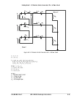
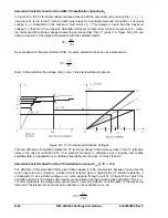
The B phase and C phase differential elements respond similarly with
IB
op1st
and
IC
op1st
substituted in the
respective equation. This unique method of second harmonic sharing is recommended to ensure proper
restraint on all phases without blocking tripping on faulted phases
.
For special transformers cases, contact the transformer manufacturer or the Basler Electric, Technical
Services Department.
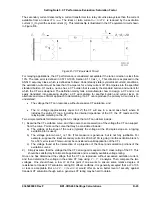
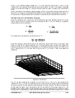
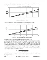
Step 1. If second harmonic sharing is enabled, set the second harmonic restraint unit setting at 18%. If
second harmonic sharing is disabled, set the second harmonic restraint unit at 12%.
Step 2. Set the fifth harmonic restraint unit setting.
5
th
= 35%
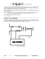
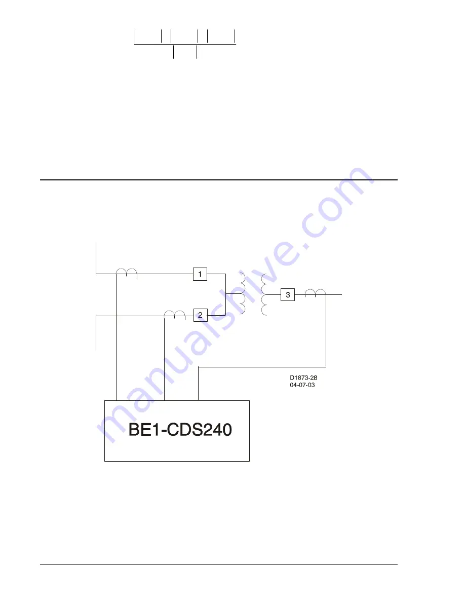
EXAMPLE 3 – DUAL BREAKERS
If a two winding transformer has two high side (or low side) breakers brought into two independent inputs
on the relay, calculate the differential settings as if breaker two in the figure below was open (see
Example 2). Then set the relay with identical settings for input 1 and input 2.
Figure D-4. Dual Breakers
D-20
BE1-CDS240 Settings Calculations
9365200990 Rev F
Summary of Contents for BE1-CDS240
Page 2: ......
Page 8: ...vi BE1 CDS240 Introduction 9365200990 Rev F This page intentionally left blank ...
Page 38: ...1 28 BE1 CDS240 General Information 9365200990 Rev F This page intentionally left blank ...
Page 40: ...ii BE1 CDS240 Quick Start 9365200990 Rev F This page intentionally left blank ...
Page 152: ...ii BE1 CDS240 Metering 9365200990 Rev F This page intentionally left blank ...
Page 226: ...iv BE1 CDS240 Application 9365200990 Rev F This page intentionally left blank ...
Page 286: ...ii BE1 CDS240 Security 9365200990 Rev F This page intentionally left blank ...
Page 290: ...9 4 BE1 CDS240 Security 9365200990 Rev F This page intentionally left blank ...
Page 292: ...ii BE1 CDS240 Human Machine Interface 9365200990 Rev F This page intentionally left blank ...
Page 306: ...10 14 BE1 CDS240 Human Machine Interface 9365200990 Rev F This page intentionally left blank ...
Page 308: ...ii BE1 CDS240 ASCII Command Interface 9365200990 Rev F This page intentionally left blank ...
Page 342: ...11 34 BE1 CDS240 ASCII Command Interface 9365200990 Rev F This page intentionally left blank ...
Page 349: ...Figure 12 5 Horizontal Rack Mount Front View 9365200990 Rev F BE1 CDS240 Installation 12 5 ...
Page 361: ...Figure 12 17 Typical DC Connection Diagrams 9365200990 Rev F BE1 CDS240 Installation 12 17 ...
Page 372: ...12 28 BE1 CDS240 Installation 9365200990 Rev F This page intentionally left blank ...
Page 468: ...13 92 BE1 CDS240 Testing and Maintenance 9365200990 Rev F This page intentionally left blank ...
Page 512: ...14 42 BE1 CDS240 BESTCOMS Software 9365200990 Rev F This page intentionally left blank ...
Page 544: ...ii BE1 CDS240 Terminal Communication 9365200990 Rev F This page intentionally left blank ...
Page 550: ...ii BE1 CDS240 Settings Calculations 9365200990 Rev F This page intentionally left blank ...
Page 578: ...D 28 BE1 CDS240 Settings Calculations 9365200990 Rev F This page intentionally left blank ...
Page 579: ......


