Setting Note 3.
CT Performance Evaluation: Saturation Factor
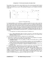
The secondary current delivered by a current transformer to a relay circuit is always less than the current
available from an ideal
CTI
S, ideal
. The ideal or ratio current
I
S
I
=I
P
/CTR
is reduced by the excitation
current (
I
e
) to yield the actual current (
I
s
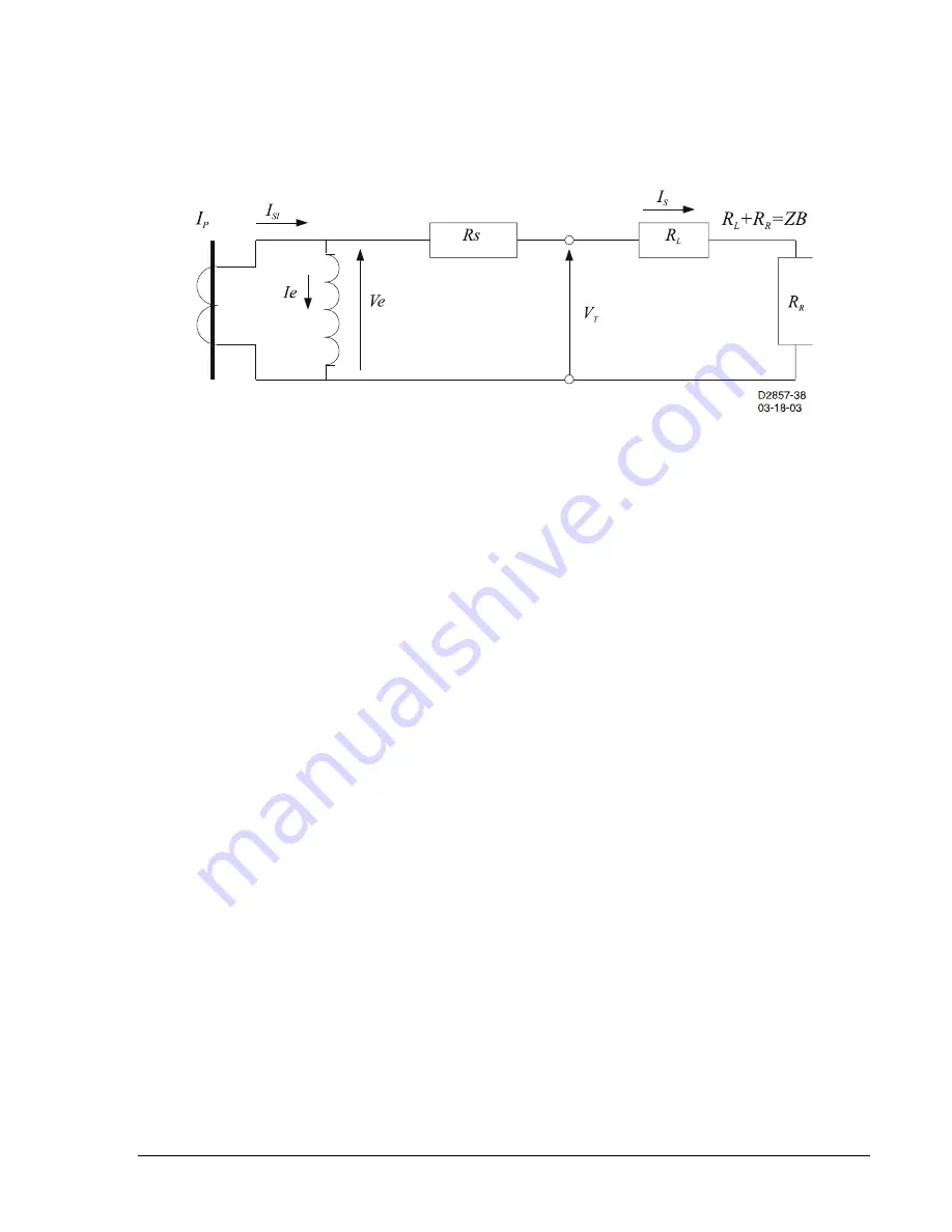
). This relationship is illustrated in the CT equivalent circuit shown
in Figure D-5.
more efficient approach to determining if a CT can reproduce the primary AC current is to
The voltage the CT can reproduce without excessive CT saturation, and
ding the internal impedance of the CT, the CT leads and the
)
of the curve (typically the voltage at the 45 degree slope on a log-log
citation branch,
at the intersection of a projection of the linear and saturation portions of the
)
e CT. This
vel of security against
transient CT saturation though such a generous CT rating may be hard to obtain.
Figure D-7. CT Equivalent Circuit
For relaying applications, the CT performance is considered acceptable if the ratio correction is less than
10%. The ratio error is defined in C57.13-1993, Section 8.1.10 as
I
e
/I
s
. This criterion is expressed in the
ANSI C accuracy class, which is defined as follows: Under steady state (symmetrical current) conditions,
the excitation current must be less than 10 amperes for a relay current of 100 amperes into the specified
standard burden. Of course, no one has a CT burden that is exactly the standard burden and current for
which the CT was designed. The definition mainly tells a manufacturer how to design a CT and is not
easily translated into assessing whether a CT will saturate for another burden and current level. An
alternate and
understand:
The
I
R
voltage (approximately equal to
I
Z
) the CT will see in a worst case fault, where R
includes the entire CT loop, inclu
relaying and metering on the CT.
Two simple methods for determining the AC voltage that a CT can deliver include:
1
Examine the CT excitation curve, and then come to some selection of the voltage the CT can support
from the curve. Points on the curve that may be considered include:
a) The voltage at the knee
excitation plot is used).
b) The voltage point where
I
e
is 10A. (This measure is generous, but is not fully justifiable. For
example, suppose the ideal secondary current is 20A but 10A is going into the ex
for a 50% error level. This would not be considered a valid application of the CT.)
c) The voltage found
excitation curves.
2
Simply assume that the voltage that the CT can support is equal to the C class rating of th
should be satisfactory for almost all applications and is a readily available voltage rating.
Once one has determined the voltage that the CT can reproduce without excessive excitation current,
and then determine the voltage in the entire CT loop using
V = I * R
analysis. Then compare the two
voltages. One should have a low
SF
at this point if one wants to ensure some relative degree of
resistance to transient CT saturation during DC offset conditions. It is generally accepted that a
SF
of 0.5
or less is acceptable. But an
SF < 1/(Fault X/R)
would offer an even better le
9365200990 Rev F
BE1-CDS240 Settings Calculations
D-23
Summary of Contents for BE1-CDS240
Page 2: ......
Page 8: ...vi BE1 CDS240 Introduction 9365200990 Rev F This page intentionally left blank ...
Page 38: ...1 28 BE1 CDS240 General Information 9365200990 Rev F This page intentionally left blank ...
Page 40: ...ii BE1 CDS240 Quick Start 9365200990 Rev F This page intentionally left blank ...
Page 152: ...ii BE1 CDS240 Metering 9365200990 Rev F This page intentionally left blank ...
Page 226: ...iv BE1 CDS240 Application 9365200990 Rev F This page intentionally left blank ...
Page 286: ...ii BE1 CDS240 Security 9365200990 Rev F This page intentionally left blank ...
Page 290: ...9 4 BE1 CDS240 Security 9365200990 Rev F This page intentionally left blank ...
Page 292: ...ii BE1 CDS240 Human Machine Interface 9365200990 Rev F This page intentionally left blank ...
Page 306: ...10 14 BE1 CDS240 Human Machine Interface 9365200990 Rev F This page intentionally left blank ...
Page 308: ...ii BE1 CDS240 ASCII Command Interface 9365200990 Rev F This page intentionally left blank ...
Page 342: ...11 34 BE1 CDS240 ASCII Command Interface 9365200990 Rev F This page intentionally left blank ...
Page 349: ...Figure 12 5 Horizontal Rack Mount Front View 9365200990 Rev F BE1 CDS240 Installation 12 5 ...
Page 361: ...Figure 12 17 Typical DC Connection Diagrams 9365200990 Rev F BE1 CDS240 Installation 12 17 ...
Page 372: ...12 28 BE1 CDS240 Installation 9365200990 Rev F This page intentionally left blank ...
Page 468: ...13 92 BE1 CDS240 Testing and Maintenance 9365200990 Rev F This page intentionally left blank ...
Page 512: ...14 42 BE1 CDS240 BESTCOMS Software 9365200990 Rev F This page intentionally left blank ...
Page 544: ...ii BE1 CDS240 Terminal Communication 9365200990 Rev F This page intentionally left blank ...
Page 550: ...ii BE1 CDS240 Settings Calculations 9365200990 Rev F This page intentionally left blank ...
Page 578: ...D 28 BE1 CDS240 Settings Calculations 9365200990 Rev F This page intentionally left blank ...
Page 579: ......


