resistance is too optimistic in this range and should be discarded in favor of the Excitation Curve method.
The absolute values of
SF
and
SF`
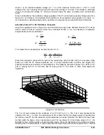
are compared in Figure D-8 for the particular case where
Zc
= 2,
ZB
=
0.5 and
R
CT
= 0.8 when
IF
varies from 0 to 100 A.
SF
IF
SF'
IF
SF and SF` for Zc=2, ZB=0.5, Rs=0.2
0.4
0.2
0
0
20
40
60
80
100
IF
Figure D-10. Comparing SF and SF`
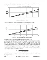
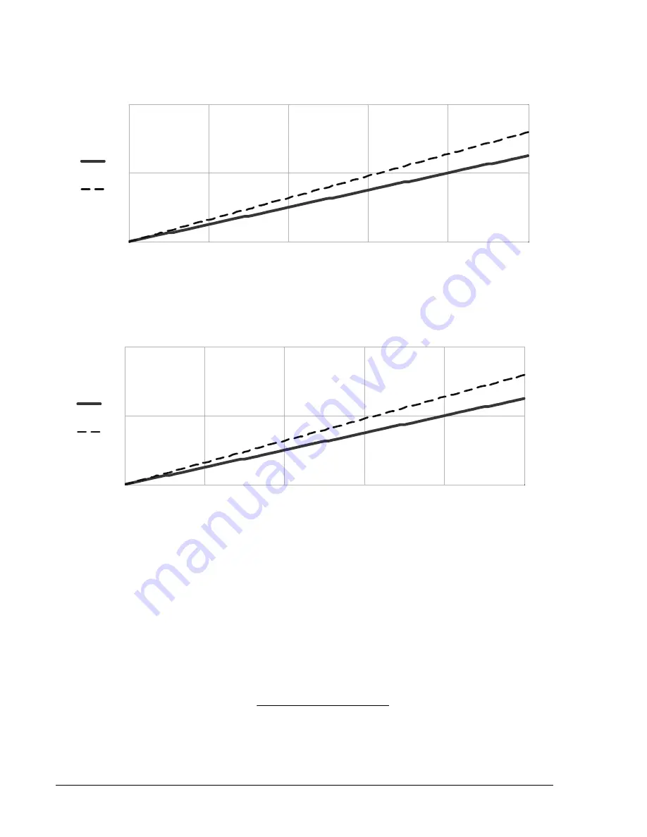
Figure D-11 illustrates how a lower
R
s value reduces the difference between SF and SF`.
SF
IF
SF'
IF
D-26
BE1-CDS240 Settings Calculations
9365200990 Rev F
Figure D-11. Reducing the Difference between SF and SF’
Saturation Factor Defined from the CT C-Class and Including CT Impedance
Likely the easiest data to obtain on a CT is its C-Class. This provides a convenient means to approximate
the maximum AC voltage that the CT can sustain. An examination of the CT excitation curve indicates
that the C-class typically falls somewhere between the 45
O
knee point voltage and the excitation voltage
at
Ie
= 10 A (i.e.,
V10
herein). Further, including the CT internal impedance in the voltage drop analysis
ensures that the CT internal resistance is not overlooked as a source of saturation. In some inexpensive
CTs or old installations, the internal resistance is not readily found in published data. But, if this is a
transformer that is being protected, it is assumed that high quality CT are being purchased or good
documentation records have been kept and hence the internal resistance of the CT is easily obtainable,
at least by examining comparably equivalent CTs. Once the C Class and the internal impedance is
btained, a third saturation factor definition is obtained:
o
Rating
Voltage
Class
-
CT C
R
ZB
IF
SF"
S
This form of
SF
should be easy to work with. It is likely the most intuitive form of
SF
and provides a
reasonably conservative yet accurate enough assessment of CT performance. This form for
SF
is used
in
the settings calculations.
IF
0
20
40
60
80
100
0
0.2
0.4
SF and SF` for Zc=2, ZB=0.5, Rs=0.2
Summary of Contents for BE1-CDS240
Page 2: ......
Page 8: ...vi BE1 CDS240 Introduction 9365200990 Rev F This page intentionally left blank ...
Page 38: ...1 28 BE1 CDS240 General Information 9365200990 Rev F This page intentionally left blank ...
Page 40: ...ii BE1 CDS240 Quick Start 9365200990 Rev F This page intentionally left blank ...
Page 152: ...ii BE1 CDS240 Metering 9365200990 Rev F This page intentionally left blank ...
Page 226: ...iv BE1 CDS240 Application 9365200990 Rev F This page intentionally left blank ...
Page 286: ...ii BE1 CDS240 Security 9365200990 Rev F This page intentionally left blank ...
Page 290: ...9 4 BE1 CDS240 Security 9365200990 Rev F This page intentionally left blank ...
Page 292: ...ii BE1 CDS240 Human Machine Interface 9365200990 Rev F This page intentionally left blank ...
Page 306: ...10 14 BE1 CDS240 Human Machine Interface 9365200990 Rev F This page intentionally left blank ...
Page 308: ...ii BE1 CDS240 ASCII Command Interface 9365200990 Rev F This page intentionally left blank ...
Page 342: ...11 34 BE1 CDS240 ASCII Command Interface 9365200990 Rev F This page intentionally left blank ...
Page 349: ...Figure 12 5 Horizontal Rack Mount Front View 9365200990 Rev F BE1 CDS240 Installation 12 5 ...
Page 361: ...Figure 12 17 Typical DC Connection Diagrams 9365200990 Rev F BE1 CDS240 Installation 12 17 ...
Page 372: ...12 28 BE1 CDS240 Installation 9365200990 Rev F This page intentionally left blank ...
Page 468: ...13 92 BE1 CDS240 Testing and Maintenance 9365200990 Rev F This page intentionally left blank ...
Page 512: ...14 42 BE1 CDS240 BESTCOMS Software 9365200990 Rev F This page intentionally left blank ...
Page 544: ...ii BE1 CDS240 Terminal Communication 9365200990 Rev F This page intentionally left blank ...
Page 550: ...ii BE1 CDS240 Settings Calculations 9365200990 Rev F This page intentionally left blank ...
Page 578: ...D 28 BE1 CDS240 Settings Calculations 9365200990 Rev F This page intentionally left blank ...
Page 579: ......


