


Additionally, as described in Section 1,
General Information, Differential Protection Application
Considerations
,
Problem 5,
if there is a ground source within the protected zone, the user can apply a
numerical, zero-sequence trap to remove the zero-sequence components from the current to prevent
misoperation on external ground faults when a ground bank is in the zone of protection. This setting is
optional. It is not required to enter a ground source setting of 1 to describe a grounded wye transformer
connection. Even though not all grounded wye transformer connections are ground sources, the relay
always assumes that a wye transformer connection is a ground source so that it is secure. Zero-
sequence current unbalance can occur in three legged core transformers due to the phantom tertiary
effect. In all cases, the relay chooses delta compensation for a wye transformer connection so that the
zero-sequence components are blocked.
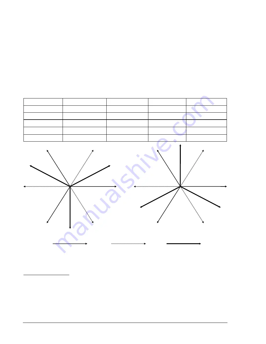
Figure 3-6 shows how the currents will be calculated for each set of current inputs for use by the phase
differential protection function. The calculation is dependent upon the phase compensation chosen as
shown in Tables 3-4, 3-5, and 3-6 and the ground source setting.
Table 3-6. Internal Compensation Chart
Compensation
Ground Source
A Phase
B Phase
C Phase
Wye (none)
0 = No
I
A
I
B
I
C
Wye (none)
1 = Yes
I
A
- I
0
I
B
- I
0
I
C
- I
0
DAB
0 = No or 1 = Yes
(I
A
- I
B
) /
3 (I
B
- I
C
) /
3 (I
C
- I
A
) /
3
DAC
0 = No or 1 = Yes
(I
A
- I
C
) /
3 (I
B
- I
A
) /
3 (I
C
- I
B
) /
3
DDAB
0 = No or 1 = Yes
(I
A
- 2I
B
+ I
C
) /3
(I
A
+ I
B
- 2I
C
) /3
(-2I
A
+ I
B
+ I
C
) /3
(I
B
-I
A
)/
3
(I
C
-I
B
)/
3
(I
A
-I
C
)/
3
I
C
-I
B
-I
A
I
B
-I
C
I
A
(I
C
-I
A
)/
3
(I
B
-I
C
)/
3
(I
A
-I
B
)/
3
-I
A
-I
C
-I
B
I
C
I
B
I
A
DAB Internal Compensation DAC
Internal
Compensation
Measured Current *(-
1)
Measured Current
Compensated Current
Figure 3-6. Internal Phase and Zero-Sequence Compensation
IEC Transformer Setup
Using BESTCOMS, navigate to the
General Operation, Transformer Setup
tab and select the
IEC Setup
button. On this screen (Figure 3-7), you can setup Windings 1 through 4. Press the
Save
button when
finished.
The IEC setup table is aimed at describing transformers that use phase shifts and winding designs that
are more commonly found outside the US market. As can be found in the IEC standards, phase and
bushing names of U, V, W, will be used generally, rather than A, B, and C, or H and X. Specifying phase
shift and transformer connection is accomplished with the D-Y-Z + clock method. For instance, a
transformer connection will be Dy1 rather than a DAB/Y, though some dual designations will be used for
3-14
BE1-CDS240 Input and Output Functions
9365200990 Rev F
Summary of Contents for BE1-CDS240
Page 2: ......
Page 8: ...vi BE1 CDS240 Introduction 9365200990 Rev F This page intentionally left blank ...
Page 38: ...1 28 BE1 CDS240 General Information 9365200990 Rev F This page intentionally left blank ...
Page 40: ...ii BE1 CDS240 Quick Start 9365200990 Rev F This page intentionally left blank ...
Page 152: ...ii BE1 CDS240 Metering 9365200990 Rev F This page intentionally left blank ...
Page 226: ...iv BE1 CDS240 Application 9365200990 Rev F This page intentionally left blank ...
Page 286: ...ii BE1 CDS240 Security 9365200990 Rev F This page intentionally left blank ...
Page 290: ...9 4 BE1 CDS240 Security 9365200990 Rev F This page intentionally left blank ...
Page 292: ...ii BE1 CDS240 Human Machine Interface 9365200990 Rev F This page intentionally left blank ...
Page 306: ...10 14 BE1 CDS240 Human Machine Interface 9365200990 Rev F This page intentionally left blank ...
Page 308: ...ii BE1 CDS240 ASCII Command Interface 9365200990 Rev F This page intentionally left blank ...
Page 342: ...11 34 BE1 CDS240 ASCII Command Interface 9365200990 Rev F This page intentionally left blank ...
Page 349: ...Figure 12 5 Horizontal Rack Mount Front View 9365200990 Rev F BE1 CDS240 Installation 12 5 ...
Page 361: ...Figure 12 17 Typical DC Connection Diagrams 9365200990 Rev F BE1 CDS240 Installation 12 17 ...
Page 372: ...12 28 BE1 CDS240 Installation 9365200990 Rev F This page intentionally left blank ...
Page 468: ...13 92 BE1 CDS240 Testing and Maintenance 9365200990 Rev F This page intentionally left blank ...
Page 512: ...14 42 BE1 CDS240 BESTCOMS Software 9365200990 Rev F This page intentionally left blank ...
Page 544: ...ii BE1 CDS240 Terminal Communication 9365200990 Rev F This page intentionally left blank ...
Page 550: ...ii BE1 CDS240 Settings Calculations 9365200990 Rev F This page intentionally left blank ...
Page 578: ...D 28 BE1 CDS240 Settings Calculations 9365200990 Rev F This page intentionally left blank ...
Page 579: ......