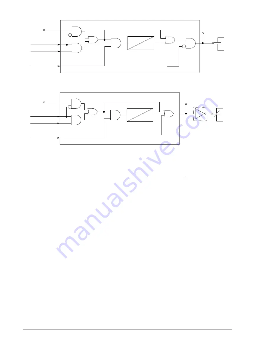
0.200 Sec
0 Sec
OR
ONE SHOT TIMER
AND
OUT[n]
HARDWARE
OUTPUT
OUTPUT
STATUS
AND
AND
OR
Control Override (0/1)
Override State (0/1)
Hold State (0/1)
VO[n]
VIRTUAL OUTPUT
CONTROLED BY SL-VO[n]
LOGIC EQUATION
HOLD ENA
(SG-HOLD COMMAND)
OUTPUT CONTROL
(CO-OUT COMMAND)
AND
ALMREL
D2647-18
08-20-98
Figure 3-9. Output Logic, General Purpose Output Contacts
0.200 Sec
0 Sec
OR
ONE SHOT TIMER
AND
OUT[A]
HARDWARE
OUTPUT
OUTPUT
STATUS
AND
AND
OR
Control Override (0/1)
Override State (0/1)
Hold State (0/1)
VO[A]
VIRTUAL OUTPUT
CONTROLED BY SL-VO[n]
LOGIC EQUATION
HOLD ENA
(SG-HOLD COMMAND)
OUTPUT CONTROL
(CO-OUT COMMAND)
ALMREL
D2647-19
08-20-98
NOT
Figure 3-10. Output Logic, Fail-Safe Alarm Output Contact
Retrieving Output Status
Output status is determined through BESTCOMS by selecting
Metering
from the
Reports
pull-down menu
and selecting the
Start Polling
button in the upper portion of the screen. Alternately, status can be
determined through the HMI Screen 1.4.2, STAT\OPER\OUT and from the ASCII command interface
using the RG-STAT command. See Section 6,
Reporting and Alarm Functions, General Status Reporting,
for more information.
Relay Trouble Alarm Disable
When the relay self-diagnostics function detects a problem in the relay, it sets internal alarm condition
ALMREL. See Section 6,
Reporting and Alarm Functions, Alarms Function
for more details on this
function. This alarm condition disables the outputs and de-energizes the OUTA relay closing the OUTA
contact.
Programmable Hold Timer
Historically, trip contact seal-in circuits have been provided in electromechanical relays. These seal-in
circuits consisted of a dc coil in series with the relay trip contact and a seal-in contact in parallel with the
trip contact. The seal-in feature serves several purposes for the electromechanical relays. One is to
provide mechanical energy to drop the target. Two is to carry the dc tripping current from the induction
disk contact, which may not have significant closing torque for a low resistance connection. Three is to
prevent the relay contact from dropping out until the current has been interrupted by the 52a contacts in
series with the trip coil. If the tripping contact opens before the dc current is interrupted, the contact may
be damaged. The first two of these items are not an issue for solid-state relays, but the third item is an
issue.
To prevent the output relay contacts from opening prematurely, a hold timer can hold the output contact
closed for a minimum of 200 milliseconds. Alternatively, if the protection engineer desires seal-in logic
with feedback from the breaker position logic, they can provide this logic by modifying the BESTlogic
expression for the tripping output. How to do this is described in Section 7,
BESTlogic Programmable
Logic, Application Tips.
The hold timer can be enabled for each input from the ASCII command input using the SG-HOLD
command. Hold timer settings are shown in Table 3-9.
3-18
BE1-CDS240 Input and Output Functions
9365200990 Rev F
Summary of Contents for BE1-CDS240
Page 2: ......
Page 8: ...vi BE1 CDS240 Introduction 9365200990 Rev F This page intentionally left blank ...
Page 38: ...1 28 BE1 CDS240 General Information 9365200990 Rev F This page intentionally left blank ...
Page 40: ...ii BE1 CDS240 Quick Start 9365200990 Rev F This page intentionally left blank ...
Page 152: ...ii BE1 CDS240 Metering 9365200990 Rev F This page intentionally left blank ...
Page 226: ...iv BE1 CDS240 Application 9365200990 Rev F This page intentionally left blank ...
Page 286: ...ii BE1 CDS240 Security 9365200990 Rev F This page intentionally left blank ...
Page 290: ...9 4 BE1 CDS240 Security 9365200990 Rev F This page intentionally left blank ...
Page 292: ...ii BE1 CDS240 Human Machine Interface 9365200990 Rev F This page intentionally left blank ...
Page 306: ...10 14 BE1 CDS240 Human Machine Interface 9365200990 Rev F This page intentionally left blank ...
Page 308: ...ii BE1 CDS240 ASCII Command Interface 9365200990 Rev F This page intentionally left blank ...
Page 342: ...11 34 BE1 CDS240 ASCII Command Interface 9365200990 Rev F This page intentionally left blank ...
Page 349: ...Figure 12 5 Horizontal Rack Mount Front View 9365200990 Rev F BE1 CDS240 Installation 12 5 ...
Page 361: ...Figure 12 17 Typical DC Connection Diagrams 9365200990 Rev F BE1 CDS240 Installation 12 17 ...
Page 372: ...12 28 BE1 CDS240 Installation 9365200990 Rev F This page intentionally left blank ...
Page 468: ...13 92 BE1 CDS240 Testing and Maintenance 9365200990 Rev F This page intentionally left blank ...
Page 512: ...14 42 BE1 CDS240 BESTCOMS Software 9365200990 Rev F This page intentionally left blank ...
Page 544: ...ii BE1 CDS240 Terminal Communication 9365200990 Rev F This page intentionally left blank ...
Page 550: ...ii BE1 CDS240 Settings Calculations 9365200990 Rev F This page intentionally left blank ...
Page 578: ...D 28 BE1 CDS240 Settings Calculations 9365200990 Rev F This page intentionally left blank ...
Page 579: ......