Camera Interface
2-8
Basler L301kc
DRAFT
2.5
Output Signals
The camera’s output signals include a pixel clock, video data, and video data qualifiers such as
line valid and data valid. In addition, an integrate enabled signal can be used to monitor the start
and stop of exposure. Sections
through
describe the output signals.
2.5.1 Pixel Clock
As shown in Figure 2-3 and in Table 2-3, the pixel clock is assigned to the TxClkIn (transmit clock)
pin of the Camera Link transmitter. The pixel clock is used to time the sampling and transmission
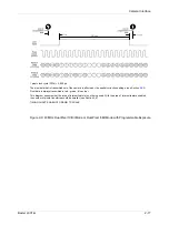
of pixel data as shown in Figure 2-4 through Figure 2-9. The transmitter used in
L301
kc
cameras
requires pixel data to be sampled and transmitted on the rising edge of the clock.
The frequency of the pixel clock is indicated in Table 1-1 on page
2.5.2 Line Valid Bit
As shown in Figure 2-4 through Figure 2-9, the line valid bit indicates that a valid line is being
transmitted. Pixel data is only valid when this bit is high.
2.5.3 Data Valid Bit
The data valid bit is not used on this camera and should be ignored. The status of this bit is always
identical to the line valid bit.
2.5.4 Video Data
Table 2-3 lists the assignment of pixel data bits to the input ports on the transmitter in the camera
and the corresponding output pins on the receiver in the frame grabber. These bit assignments
comply with the Camera Link standard. As shown in the table, the bit assignments for pixel data
vary depending on the output mode setting of the camera. The available output modes are
explained in more detail in Section
Table 2-3 also shows the assignment for the line valid bit, the data valid bit and the pixel clock.
These assignments are constant for all output modes.
L
Note that the timing used for sampling the data at the Camera Link receiver in the
frame grabber varies from device to device. On some receivers, data must be sam-
pled on the rising edge of the pixel clock (receive clock), and on others, it must be
sampled on the falling edge. Also, some devices are available which allow you to
select either rising edge or falling edge sampling. Please consult the data sheet for
the receiver that you are using for specific timing information.
Summary of Contents for L301kc
Page 1: ...Basler L301kc USER S MANUAL Document Number DA00051806 Release Date 13 July 2007...
Page 4: ......
Page 14: ...Introduction 1 6 Baslert L301kc DRAFT...
Page 20: ...Camera Interface 2 6 Basler L301kc DRAFT Figure 2 3 Camera Frame Grabber Interface...
Page 102: ...Configuring the Camera 4 32 Basler L301kc DRAFT...
Page 116: ...Troubleshooting 6 10 Basler L301kc DRAFT...
Page 118: ...Revision History ii Basler L301kc DRAFT...
Page 120: ...Feedback iv Basler L301kc DRAFT...
Page 124: ...Index viii Basler L301kc DRAFT...


