Operation and Features
3-12
Basler L301kc
DRAFT
3.5.3 System Design Requirements for Proper
Spatial Correction
, spatial correction is
used to align color information in the image. For a
given area on the object to be captured correctly,
its image must fall precisely on the red line, the
green line, and the blue line in the sensor.
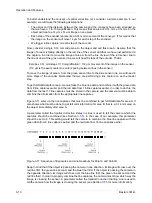
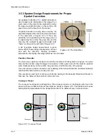
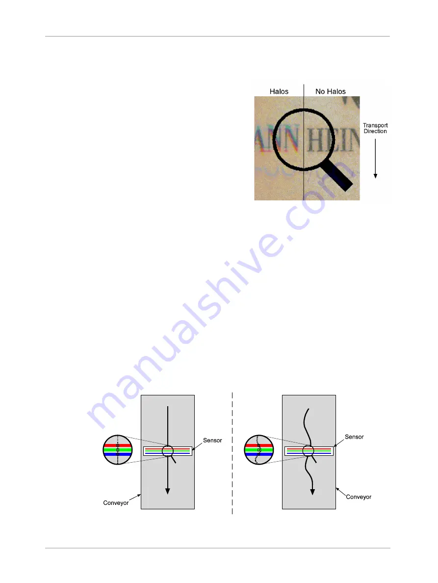
If spatial correction is being done correctly, the
captured images will be sharp and clear as shown
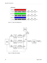
in the right side of Figure 3-12. If there are
variations in the positioning of the image when it
is captured by the red line, the green line, and the
blue line, the captured images will include color
“halos” as shown in the left side of Figure 3-12.
A list of system design requirements is given
below. When these design requirements are met
and with the camera’s shading correction
parameters set properly, the image will show no color halos.
Position Encoder
You must use a position encoder to monitor the movement of the system’s conveyor. You must
also use the encoder output to trigger line capture so that a given area of the object is captured
when it falls precisely on the red line, the green line, and the blue line of the sensor.
If you do not use a position encoder, severe haloing in the transport direction will almost certainly
result and the halos will vary in size and color.
If an encoder is used but it is not set-up correctly, haloing in the transport direction will result. In
this case, the halos will be constant in size and color.
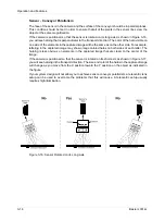
Conveyor Travel
The conveyor must travel in a straight line. If the conveyor motion is not straight, each line in the
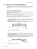
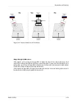
sensor will scan a different area of the object as shown in Figure 3-13. This situation will cause
haloing that is perpendicular to the transport direction. The halos will vary in size and color.
Figure 3-13: Conveyor Travel
Figure 3-12: The Halo Effect
Summary of Contents for L301kc
Page 1: ...Basler L301kc USER S MANUAL Document Number DA00051806 Release Date 13 July 2007...
Page 4: ......
Page 14: ...Introduction 1 6 Baslert L301kc DRAFT...
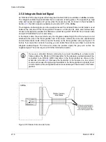
Page 20: ...Camera Interface 2 6 Basler L301kc DRAFT Figure 2 3 Camera Frame Grabber Interface...
Page 102: ...Configuring the Camera 4 32 Basler L301kc DRAFT...
Page 116: ...Troubleshooting 6 10 Basler L301kc DRAFT...
Page 118: ...Revision History ii Basler L301kc DRAFT...
Page 120: ...Feedback iv Basler L301kc DRAFT...
Page 124: ...Index viii Basler L301kc DRAFT...

