6
Q
T
Y
4
:
3
/8
x
3
.7
5
"
b
o
lt
s
("
7
")
Q
T
Y
4
:
3
/8
n
y
lo
n
in
s
e
rt
lo
c
k
n
u
ts
("
1
")
Q
T
Y
8
:
3
/8
fl
a
t
w
a
s
h
e
rs
("
2
")
Q
T
Y
4
:
l
e
g
P
p
in
s
("
1
1
")
Q
T
Y
4
:
1
/2
x
1
.0
"
b
o
lt
s
("
1
7
")
1
1
1
2
3
1
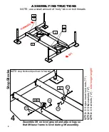
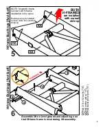
NOTE: assemble lift on level ground
and adjust legs so that lift base
frame is level during lift assembly.
1
7+2
NOTE: use a small amount of 'moly' lube on bolt threads
ASSEMBLY INSTRUCTIONS
F
e
e
t
a
n
d
L
e
g
s
[
4
p
la
c
e
s
]
Assemble lift on level ground and adjust legs so
that lift base frame is level during lift assembly.
AA
BB
NOTE:
the 3 different holes shown
can be used for pin “11” to
allow fine height adjustment
after installation
11
1+2
DOWN
to lock
17
NOTE:
do not tighten bolt “17” until Step 12
7
Q
T
Y
4
:
3
/8
x
3
.7
5
"
b
o
lt
s
("
7
")
Q
T
Y
8
:
3
/8
fl
a
t
w
a
s
h
e
rs
("
2
")
Q
T
Y
4
:
3
/8
n
y
lo
n
in
s
e
rt
lo
c
k
n
u
ts
("
1
")
Q
T
Y
4
:
3
/8
x
3
.7
5
"
b
o
lt
s
("
7
")
Q
T
Y
8
:
3
/8
fl
a
t
w
a
s
h
e
rs
("
2
")
Q
T
Y
4
:
3
/8
n
y
lo
n
in
s
e
rt
lo
c
k
n
u
ts
("
1
")
F
o
rw
a
rd
C
ro
s
s
m
e
m
b
e
r
2
3
Assemble lift on level ground and adjust legs so
that lift base frame is level during lift assembly.
Assemble lift on level ground and adjust legs so
that lift base frame is level during lift assembly.
CC
DD
1+2
7+2
A
ft
C
ro
s
s
m
e
m
b
e
r
3
DD
1+2
7+2

