background image

PAGE 4

ITEM

PART NO.

DESCRIPTION

QTY.

Forward H-Frame (8k

72

)

Forward H-Frame (8k

6

)

Forward H-Frame (8k

53

)

Bunk Board Assembly

Bunk Rail

Adjustable Support Leg

6
6
6
7
8
9

1
1
1
2
2
4

A431-0046
A431-0016
A431-0028
A428-0002
A427-0004
K200-0012

PART NO.

DESCRIPTION

QTY.

ITEM

W110-0025

Aft Crossmember

1
2
3
3
4
4
5

W110-0024
W104-0020
W104-0028
W104-0021
W104-0029

A431-0045 

Forward Crossmember

Left Side Rail (8k

53

 & 8k

65

)

Left Side Rail (8k

72

)

Right Side Rail (8k

53

 & 8Wk

65

)

Right Side Rail (8k

72

)

Aft H-Frame (8k

72

)

1
1
1
1
1
1
1

10

4

W116-0001

PART NO.

DESCRIPTION

QTY.

ITEM

S103-0506

Hex Cap Screw 3/8 x 1-1/4 SS

A
A
A
B
C
C
C

S362-0008
S313-0008
S166-6812
S103-0919
S362-0012
S313-0013 

Nylon Insert Lock Nut 3/8 SS

Washer Flat 3/8 SS

Hex Set Screw 5/8 x 1 1/2 SS

Hex Cap Screw 3/4 x 8-1/2 SS

Nylon Insert Lock Nut 3/4 SS

Washer Flat 3/4 SS

24
24
48
12

4
4
4

D
D
D

S103-0911
S362-0012
S313-0013

Hex Cap Screw 3/4 x 5 SS

Nylon Insert Lock Nut 3/4 SS

Washer Flat 3/4 SS

4
4
4

PART NO.

DESCRIPTION

QTY.

ITEM

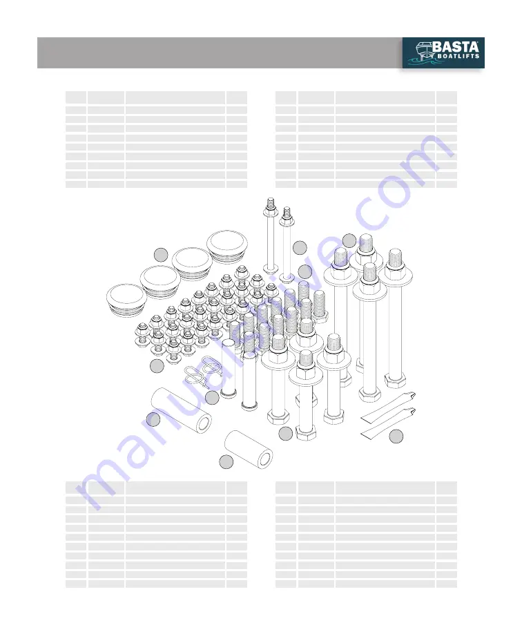
F730-0006

Plastic Cap 2-3/8 Round

E
F
F

G
G
G
H

S503-0013
S522-0801
S103-0518
S362-0008
S313-0008
Y356-0003

Clevis Pin 3/4 x 3-1/2 SS

Ring Type Cotter Pin SS

Hex Cap Screw 3/8 x 4-1/2 SS

Nylon Insert Lock Nut 3/8 SS

Washer Flat 3/8 SS

Anti-seize Grease Packet

4
2
2
2
2
4
2

J

K

N/A

M620-1001
M620-1002

L129-0001

H-frame Bushing (service part)

Bunk Rail Bushing (service part)

Key Fob Floats

4
4
2

H

Foot Pad

Hydraulic Cylinder Kit

11

1

H310-0021

5
5

A431-0015
A431-0027 

Aft H-Frame (8k

65

)

Aft H-Frame (8k

53

)

1
1

12

2

W106-0001

Stop Tube

A

J

F

K

D

E

G

C

B

PARTS LIST - BOAT LIFT

Summary of Contents for 8k53

Page 1: ...COPYRIGHT 2022 BASTA INC 3 22 L392 0103C BASTA BOATLIFTS OVER CENTER GALVANIZED STEEL LIFT 8 000 lb Capacity Boat Lift Models 8k53 8k65 8k72 866 GoBasta GoBasta com...

Page 2: ...ous injury or death Always use AGM batteries and follow battery manufacturer s warnings and instructions Improper use or use of other batteries have the potential to produce flammable hydrogen gas whi...

Page 3: ...P 16 REMOTE CONTROL FOB INFORMATION P 17 TROUBLESHOOTING FAQ P 18 MAINTENANCE P 19 WARRANTY P 20 PRODUCT INFORMATION Model Serial Purchased From Date of Purchase Contact Name Phone Notes IMPORTANT WA...

Page 4: ...ert Lock Nut 3 8 SS Washer Flat 3 8 SS Hex Set Screw 5 8 x 1 1 2 SS Hex Cap Screw 3 4 x 8 1 2 SS Nylon Insert Lock Nut 3 4 SS Washer Flat 3 4 SS 24 24 48 12 4 4 4 D D D S103 0911 S362 0012 S313 0013 H...

Page 5: ...l 9 16 ratchet 9 16 box end wrench Large slip joint pliers Medium sized adjustable wrench AA a 1 R812 0011 PART NO R283 0002 R310 0001 R310 0002 Remote Control Master Unit DESCRIPTION Solar Controller...

Page 6: ...n bolt threads through the assembly process PAGE 6 3 3 1 1 1 1 2 2 Tighten set screws A B alternately to push leg securely into corner of leg socket A B QTY 12 5 8 x 1 1 2 hex head set screws Assemble...

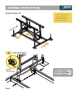
Page 7: ...2 Forward Crossmember Aft Crossmember 3 PAGE 7 QTY 8 3 8 x 1 1 4 bolts QTY 16 3 8 flat washers QTY 8 3 8 lock nuts QTY 8 3 8 x 1 1 4 bolts QTY 16 3 8 flat washers QTY 8 3 8 lock nuts...

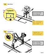
Page 8: ...ured Steps 4 6 Forward H Frame Use a small amount of moly lube on bolt threads through the assembly process PAGE 8 5 6 4 QTY 2 3 4 x 8 bolts QTY 2 3 4 flat washers QTY 2 3 4 lock nuts ASSEMBLY INSTRUC...

Page 9: ...53 USE TOP HOLES 8k65 USE BOTTOM 8K72 HOLES QTY 2 3 4 x 4 3 4 bolts QTY 4 3 8 flat washers QTY 2 3 8 lock nuts QTY 2 3 4 x 8 bolts QTY 2 3 4 flat washers QTY 2 3 4 lock nuts Bushings are pre installed...

Page 10: ...ctured Steps 7 9 7 Use a small amount of moly lube on bolt threads through the assembly process PAGE 10 9 7 8 8 9 QTY 2 3 4x 3 1 2 clevis pins QTY 2 ring type cotter pins IMPORTANT Install cylinder wi...

Page 11: ...hers QTY 4 3 4 lock nuts After the bunks are installed adjust the frame to be square and level then tighten bolts Install bunks with lift in down position QTY 4 3 8 x 1 1 4 bolts QTY 8 3 8 flat washer...

Page 12: ...Connect the Red Battery Cable to the positive terminal and the Black Battery Cable to the negative terminal Step 4 Before moving into the water test the lift on dry ground using the Up Down Switch an...

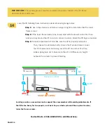
Page 13: ...x to separate it from the lift Move the lift to final destination Use this diagram to help place the lift Lift placement should be so that the top of the aft end of the bunks are one foot above the hi...

Page 14: ...ep 3 To make adjustments first make sure the lift is properly supported Then loosen the anti sway bolts remove the P pin and raise or lower the lift crossmember on the leg Level the lift one corner at...

Page 15: ...ling occurs STOP carefully lower the lift to remove the boat and re level the lift Continue repeating this step until the lift can be raised into the full Over Center position without settling 2 Remov...

Page 16: ...lift according to recommended Maintenance page 19 Only use Basta Boatlifts approved fluid in lift Contact Basta Boatlifts or authorized dealer for approved biodegradable hydraulic fluid When not in us...

Page 17: ...acturer LOW BATTERY LOCKOUT The remote control contains a low voltage lockout which is intended to protect the lift s battery from over discharge When the battery drops below the low battery threshold...

Page 18: ...ee Page 12 A Check the fluid level See Page 19 Q DOES THE LIFT HAVE TO GO ALL THE WAY UP A YES in order for your lift to function as intended the lift must ALWAYS be stored in the full upright positio...

Page 19: ...DOWN POSITION Hydraulic fluid shown with lift in the DOWN position one inch 1 EVERY 6 MONTHS WE RECOMMEND Inspect hoses cylinders and fittings for leaks and wear Check wire terminals for snugness and...

Page 20: ...rk to be provided by the Company s Authorized dealer for a period of 3 years from Warranty Start Date provided there is an active Authorized Dealer within 50 miles of the location of the Product Labor...

Reviews: