Installation & Maintenance Manual: BRBAC 1 HP
Published December 2019
Rev.A1
32
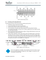
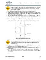
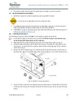
Figure 25: BRBAC 1 HP drive motor connection - exploded view
ZiPline Conveyor highly recommends using a lift table or equivalent equipment to
remove the motor from the drive section. Improper handling of the motor can cause
damage and increase risk of injury.
7.
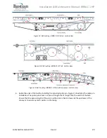
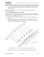
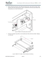
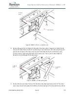
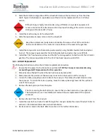
Remove the underside cover closest to the drive pulley from the drive section. The underside
cover closest to the drive pulley is attached by (4) 3/8” carriage bolts and serrated flange nuts
and (4) 1/4
” hex head cap screws and clip on nuts.
Figure 26 illustrates the location of the
underside cover and corresponding hardware on the motor side. The non-motor side is identical
except for the shaft length of the drive pulley.
AC drive motor
and gearbox
1 HP drive
pulley
7/16” hex head
cap screw
M8 shoulder bolt
Torque arm
Summary of Contents for BRBAC 1 HP
Page 1: ...Installation and Maintenance Manual Model BRBAC 1 HP Effective December 2019 Rev A1...
Page 44: ...Installation Maintenance Manual BRBAC 1 HP Published December 2019 Rev A1 44...
Page 45: ...Installation Maintenance Manual BRBAC 1 HP Published December 2019 Rev A1 45...
Page 46: ...Installation Maintenance Manual BRBAC 1 HP Published December 2019 Rev A1 46...
Page 47: ...Installation Maintenance Manual BRBAC 1 HP Published December 2019 Rev A1 47...

