Installation & Maintenance Manual: BRBAC 1 HP
Published December 2019
Rev.A1
34
10.
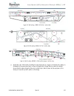
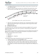
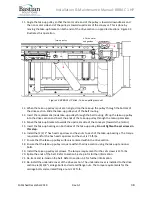
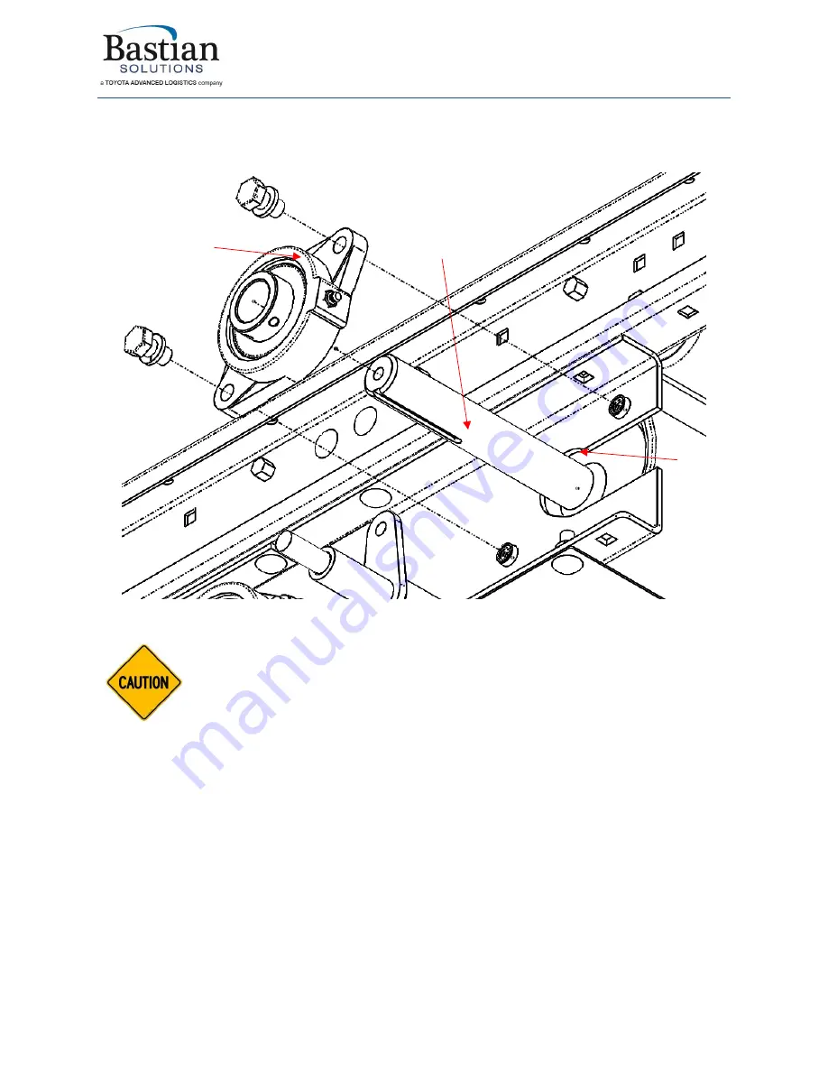
Slide out the bearings from the drive pulley shaft. Figure 28 illustrates the location of the drive
pulley bearing and the corresponding hardware on the motor side. The non-motor side is
identical except for the shaft length of the drive pulley.
Figure 28: BRBAC 1 HP drive pulley bearing
The set screws used in the drive pulley bearings cause an indent on the shaft on
install. ZiPline Conveyor advises caution when removing the bearings to avoid damage.
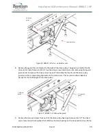
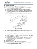
11.
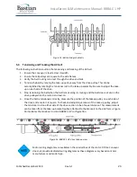
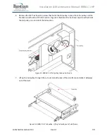
Pull the drive pulley out through the cut out of the drive section side frame. The belt should
have enough slack to pull the drive pulley out of the side frame. Figure 29 illustrates the drive
pulley removal from the drive section on the motor side. The non-motor side is identical except
for the shaft length of the drive pulley.
1 HP drive
pulley
Side frame
cutout
Drive pulley
bearing
Summary of Contents for BRBAC 1 HP
Page 1: ...Installation and Maintenance Manual Model BRBAC 1 HP Effective December 2019 Rev A1...
Page 44: ...Installation Maintenance Manual BRBAC 1 HP Published December 2019 Rev A1 44...
Page 45: ...Installation Maintenance Manual BRBAC 1 HP Published December 2019 Rev A1 45...
Page 46: ...Installation Maintenance Manual BRBAC 1 HP Published December 2019 Rev A1 46...
Page 47: ...Installation Maintenance Manual BRBAC 1 HP Published December 2019 Rev A1 47...


