Installation & Maintenance Manual: BRBAC 1 HP
Published December 2019
Rev.A1
33
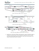
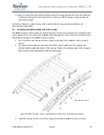
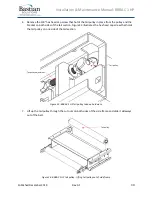
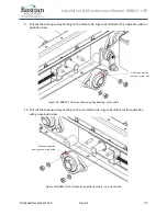
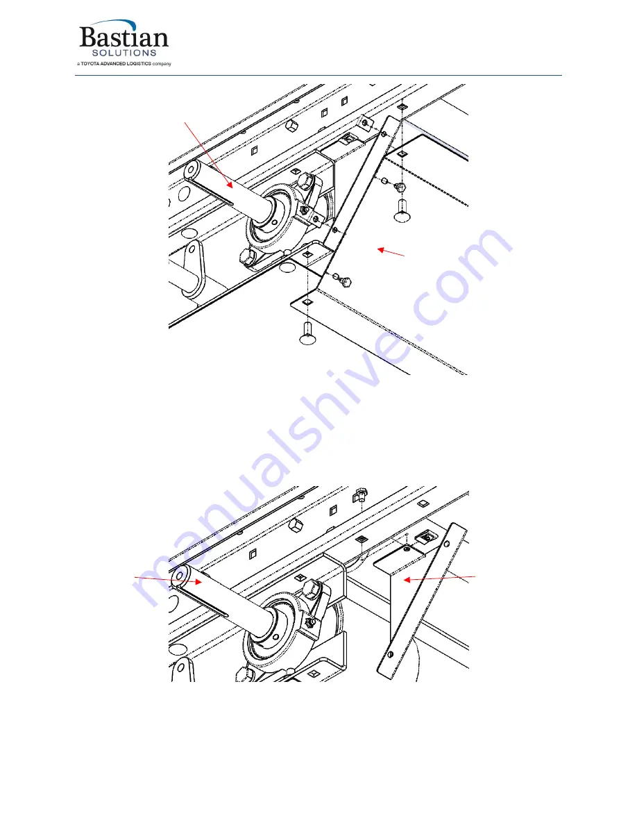
Figure 26: BRBAC 1 HP drive - underside cover
8.
Remove the guard that is attached to the back of the drive pulley. The guard is attached to the
drive section side frame via (2) 1/4
” hex head cap screws and clip
-on nuts. Removing this guard
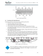
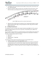
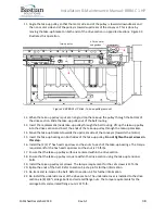
gives access to remove the drive pulley. Figure 27 illustrates the location of the drive pulley
guard and the corresponding hardware on the motor side. The non-motor side is identical
except for the shaft length of the drive pulley.
Figure 27: BRBAC 1 HP drive pulley guard
9.
Remove the two set screws from each of the drive pulley bearings. Remove the 1/2
” hex head
cap screw and split lock washer that attaches the drive bearings to the drive section drive frame.
1 HP drive
pulley
Underside cover
1 HP drive
pulley
Drive pulley
guard
Summary of Contents for BRBAC 1 HP
Page 1: ...Installation and Maintenance Manual Model BRBAC 1 HP Effective December 2019 Rev A1...
Page 44: ...Installation Maintenance Manual BRBAC 1 HP Published December 2019 Rev A1 44...
Page 45: ...Installation Maintenance Manual BRBAC 1 HP Published December 2019 Rev A1 45...
Page 46: ...Installation Maintenance Manual BRBAC 1 HP Published December 2019 Rev A1 46...
Page 47: ...Installation Maintenance Manual BRBAC 1 HP Published December 2019 Rev A1 47...

