Installation and Maintenance Manual: RLVAC
Published February 2022
31
4. Secure each module with (4x) 1/4”-20 SHCS, item (32) in Figure 19: Return Roller Module
Installation Detail. See Table 7: Fastener Standard Torque Values in section 6.3 for tightening
torque.
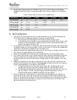
Table 4: Return Roller Positions for Intermediate Beds
ZONES PER BED
1 ZONE 2 ZONES
3 ZONES
4 ZONES
5 ZONES
6 ZONES
18” Zone Length
N/A
18
18
18, 54
18, 72
36, 72
24” Zone Length
N/A
12, 36
12, 60
36, 60
36, 84
30” Zone Length
N/A
12, 42
12, 72
12, 72
36” Zone Length
N/A
18, 54
18, 90
60” Zone Length
30
30, 90
5.7 Belt Tracking Zones
1. Conveyors with a total length of 60 feet or longer will receive one or more belt tracking zones.
The tracking zones are shipped separately as a kit and are field installed.
a. See the system layout drawing for exact locations of these tracking zones.
b. Typical tracking zone locations are evenly spaced along the length of the conveyor, with
a maximum of 60 feet between a tracking zone and a tail or skew start/end section, or
between two adjacent tracking zones.
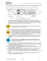
2. The tracking zone kit consists of a heavy duty roller with adjustment brackets, and carrying rollers
and bands to replace the conveying rollers in the zone. See Figure 22: RLVAC Intermediate Bed
which shows a tracking zone installed next to a standard zone.
3. Identify the zone(s) to be replaced with tracking zones, and remove all conveying rollers from the
zone. Remove the finger guards if the zone has them.
4. Remove the adjustable center pressure roller and brackets (30) from the pressure module.
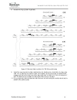
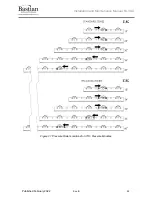
5. On 2” roller center conveyor, move the fixed pressure rollers nearest the adjustable center roller
location to match the roller locations shown in Figure 20: Pressure Roller Locations for 2”RC
Pressure Modules. No pressure rollers may be installed within 6” of the adjustable center roller
location.
6. Replace the adjustable center pressure roller with the heavy duty roller (23) and brackets (25)
provided in the tracking zone kit. Route the belt underneath the heavy duty roller. See Figure 22:
RLVAC Intermediate Bed for an example of belt routing.
a. The tracking bands for the heavy duty roller are item (24). Tracking bands are pre-
installed when the heavy duty roller is supplied as part of a belt tracking zone kit.
b. The hardware included with the tracking zone kit is shown as items (26), (27), (28), and
(29). See Table 11: RLVAC General Arrangement BOM in Appendix 2: General
Arrangement Drawings for detailed descriptions and part numbers.
7. Adjust the heavy duty roller location to the correct side of the adjustable center roller slot, as
shown by the arrows in Figure 20: Pressure Roller Locations for 2”RC Pressure Modules and
Figure 21: Pressure Roller Locations for 3”RC Pressure Modules. Ensure the heavy duty roller is
square to the pressure module frame by moving it to the end of its travel on both sides, then
tighten the brackets and roller fasteners.

