Installation and Maintenance Manual: RLVAC
Published February 2022
36
VFD settings should only be adjusted by qualified personnel. Improper VFD settings
can prevent correct emergency stop operation or cause hazardous unintended motion.
5.11 Accessories
Attach any applicable accessories and connecting hardware (e.g. guiderail) to the mounted conveyor
section at this point.
Refer to the “Bastian Solutions Conveyor - Side Cover and Guiderail Installation
Manual” for more information on installing most accessories.
5.12 Belt Tensioning and Tracking
Belt tensioning procedures are different depending on whether the conveyor has a screw takeup or
pneumatic takeup, but belt tracking is performed the same way in all cases.
5.12.1 Screw Takeup Drives
1. Once the belt is installed and joined, and all return rollers and tracking rollers have been installed,
then the belt may be tensioned.
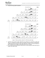
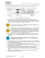
2. See Figure 24: Screw Takeup Drive Belt Routing, which is a duplicate of the same figure from
section 5.5.1 for easier reference.
3. Ensure the takeup jam nuts are loosened where both takeup screws turn freely.
4. Back off both sleeve jam nuts several inches away from the plastic spring sleeves.
5. Alternately turn the takeup screws clockwise to tighten the belt. It is important to turn both screws
the same amount to keep the takeup carriage square to the frame and prevent it from binding.
6. As the takeup carriage moves away from the drive pulley, the spring sleeves will move with it.
Periodically check and back off the sleeve jam nuts as needed to provide space for the sleeves to
move.
7. Once the belt starts getting tight, monitor the tension indicators on the takeup brackets for
appropriate tension.
8. If the belt is joined with lacing, use the inner set of tension window indicators. If the belt is joined
with a hot splice, use the outer set of tension window indicators. See Figure 25: Tension

