Installation and Maintenance Manual: RLVAC
Published February 2022
48
5. Remove the old takeup spring (68) and/or the old guide tube (69), and insert the replacement
spring or guide tube.
6. Reassemble the tensioner screw (70), takeup spring (68), guide tube (69), and tension indicator
weldment (71).
7. See section 5.12.1 for belt tensioning and tracking instructions.
8. Replace any guards that were removed.
6.5.5 Idler Roller Replacement
1. Remove the side guards on both sides of the screw takeup. See Figure 31: General
Arrangement, Belt Under Roller AC, Screw Takeup Drive, Sheet 1 of 1 for details.
2. Loosen the tensioner jam nuts, then turn both tensioner screws (70) counterclockwise until all belt
tension is released. Ensure that both screws are adjusted evenly to prevent binding.
3. Remove the underside guard on the drive section. For conveyors where access from underneath
is restricted, remove conveying rollers and one pressure module instead. See section 6.8 for
details.
4. Unbolt the affected roller (46) or (47) from both sides of the drive, and lower or raise it until it can
be slid out from the belt.
5. Insert the replacement roller (46) or (47). Note that item (46) is a crowned roller, which can be
identified by the shiny machined surface. The crown is very slight and will generally not be visible
without a straightedge to compare against. Item (47) is a non-crowned roller with a mill finish
tube.
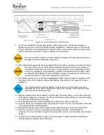
6. Verify correct belt routing using the arrows on the side of the drive section. See Figure 24: Screw
Takeup Drive Belt Routing in section 5.12.1 for confirmation.
7. Replace the bolt and lock washer on both sides of the roller. If the adjustment brackets were not
moved during the procedure, the previous tracking setting may be maintained; otherwise, set the
roller square to the conveyor frame.
8. See section 5.12.1 for belt tensioning and tracking instructions.
9. Replace any guards or conveying rollers that were removed.
6.5.6 Bearing Replacement and Maintenance
1. Periodically grease each bearing following the instructions in the ABB Motors MN3016 bearing
manual. Do not over-lubricate. Too much grease can damage bearing seals or cause excessive
heating.
2. If bearing replacement is necessary, follow the instructions in section 6.5.2 for the drive pulley
bearings (49), or in section 6.5.3 for the takeup pulley bearings (66).
6.6 Pneumatic Takeup Drive
See Figure 30: General Arrangement, Belt Under Roller AC, Pneumatic Takeup Drive, Sheet 1 of 1 in
Appendix 2: General Arrangement Drawings for exploded views and part numbers.
Turn off and lock out both the drive motor and the air supply to the takeup cylinder
before removing guards or replacing any parts on the drive module.
6.6.1 Drive Motor Replacement
1. Before removing the existing motor, check motor and gearbox nameplates to verify that the
replacement motor is the correct shaft size, gear ratio, and voltage.
2. Verify that electrical power is not present and is properly locked out, then disconnect the electrical
connections in the motor conduit box. Note the phase rotation for later so the replacement motor
will spin the same direction.


