background image

English

10

Before installation

The telescopic loft ladder is 

perfectly safe when correctly 
installed and will support a weight 

of up to 150 Kgs. Please observe 

the following safety procedures:


Do not attempt to climb your loft 
ladder until installation is 

complete.


Use a second ladder to gain 

access to the loft while carrying 

out the work. Ensure that this is 
stable.


During installation and operation, 

follow all instructions step by 

step to ensure your safety and 

optimum performance of the loft 
ladder.


When installation is complete, 

before using the ladder make 
sure that it is pulled fully down 
and both feet are resting firmly 
on the floor and that the locking 
mechanism is properly engaged. 
Observe the instructions for the 
optimum safe working angle.


Observe normal safety 
precautions when working in the 
loft space. Place weight only on 
the main ceiling joists. Do not 
drill above head height. Avoid 
contact with electrical wiring.


Ensure someone else is on the 
premises and knows where you 
are in case of an accident.


Do not modify any component 
supplied with this product or 

substitute any loft ladder 

component with anything other 

than genuine replacement parts.

Installation

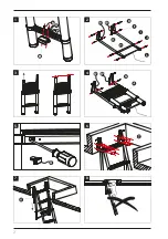
Mounting the stowage hook

(See 

Fig. 1

).

1.  Place the stowage hook 

(M)

 in 

position on the rear side of the 

bottom rung and align their 
holes.

2.  Fasten the screws 

(N)

 together 

with the spring washer 

(O) 

and 

washer 

(P) 

tightly.

Install the stowage frame

(See 

Fig. 2

).

1.  Place one of the stowage frame 

tube 

(E)

 in position on the 

Mounting bracket 

(B1, B2)


shorter swivel arm and align 
their holes.

2.  From the outer edge, guide the 

bolt 

(F)

 through mounting holes.

3.  Fasten the bolts with the nuts.
4.  Repeat this procedure to fix the 

other stowage frame tube 

(E)

.

Install the spring bolt and 

carrier tube

(See 

Fig. 2

).

Prior to fitting, measure and make 
note of the ceiling height "H" where 
you will be installing your loft 
ladder. Use 

Table 1

 to identify the 

Summary of Contents for 7063996

Page 1: ...gnes d installation Installatie instructies Guida all installazione Instrucciones de instalaci n Instru es de instala o Instrukcje monta u Teleskopische Dachbodenleiter chelle de grenier t lescopique...

Page 2: ...2 N O P 1 2 Q 1 2 7 5 3 8 6 4 1 2...

Page 3: ...3 13 12 11 9 10 12a 13a 12b 13b...

Page 4: ...4 17 18 16 15 14...

Page 5: ...B H 244 261 cm L 102 5 cm W 60 cm 1 2 3 4 5 1 2 3 4 5 Spring Hole B H 249 266 cm L 107 5 cm W 60 cm 1 2 3 4 5 1 2 3 4 5 Spring Hole A H a t c h W i d t h W Hatch Length L Ceiling Height H Loft Joist...

Page 6: ...ge der Leiter 15 Montage der Dachbodenleiter 16 Montage der Feder 17 Die Leiter ausziehen 17 Die Leiter einschieben 17 Pack contents product parts A Ladder B Left right mounting bracket C Mounting bra...

Page 7: ...tube porteur 20 Montage de l chelle 20 Montage de l chelle de grenier 21 Montage du ressort 22 Ouverture de l chelle 22 Fermeture de l chelle 22 Inhoud Overzicht 2 Inhoud van de verpakking onderdelen...

Page 8: ...supporto 2 M8x50 a brugola K Molle 2 L Laccetto M Gancio di chiusura N Viti 2 M5x12 O Rondelle elastiche 2 M5 P Rondelle 2 M5 Q Tappi di copertura 2 Contenido del paquete piezas del producto A Escaler...

Page 9: ...nakr tka 4 M6x40 G ruba i nakr tka 4 M6x45 H Rura no na 2 I ruba spr yny rury ramy 2 M8 J ruba rury no nej 2 M8x50 imbus K Spr yna 2 L Pas M Zaczep do chowania N ruba 2 M5x12 O Podk adka spr ysta 2 M5...

Page 10: ...n ceiling joists Do not drill above head height Avoid contact with electrical wiring Ensure someone else is on the premises and knows where you are in case of an accident Do not modify any component s...

Page 11: ...height and ensure you have sufficient clearance Hatch length L and Hatch width W for the ladder to be installed in the loft hatch 1 Slide the safety lock towards the center of the rung using a screwd...

Page 12: ...a second ladder to gain access to the loft while carrying out the work Ensure that this is stable Mounting the spring See Fig 7 There is groove at each end of the frame tube spring bolt I to hold the...

Page 13: ...if required 2 Release the sliding safety locks at the bottom Fig 14 3 Grip the lower stiles and push up Fig 15 Unlock and close the remaining rung sections automatically starting from the bottom and...

Page 14: ...ie die Leiter benutzen Beachten Sie die Anweisungen f r den optimalen sicheren Anstellwinkel Beachten Sie die blichen Sicherheitshinweise f r Arbeiten auf dem Dachboden Belasten Sie nur die Hauptdecke...

Page 15: ...uerrohr H durch die beiden Tragrahmenrohre E 4 Positionieren Sie es so aus dass die Bohrungen des Tragrahmenrohrs E und des Querrohrs H aneinander ausgerichtet sind 5 F hren Sie die Rahmenrohr Federbo...

Page 16: ...gelungsposition befinden siehe Abb 12 und Abb 13 3 Ziehen Sie die Leiter Abschnitt f r Abschnitt aus bis sie vollst ndig ausgezogen ist 4 Bringen Sie die Leiter in Montageposition F hren Sie die Halte...

Page 17: ...9 Die Feder schwenkt die Leiter herab Abb 10 2 Dr cken Sie die unteren Holme der Leiter etwas nach oben um den Stauhaken der Leiter auf der R ckseite der Sprosse aus dem Querrohr des Rahmens zu l sen...

Page 18: ...rts und haken Sie den Stauhaken der sich an der R ckseite der Sprosse befindet in das Querrohr des Tragrahmens ein Abb 16 6 Dr cken Sie die Leiter aufw rts Ziehen Sie die Federn in die waagerechte Lag...

Page 19: ...pour obtenir l angle de travail pr sentant une s curit optimale Respectez les consignes de s curit normales lorsque vous travaillez dans le grenier Placer le poids uniquement sur les solives du plafon...

Page 20: ...tube de cadre de rangement E et du tube porteur H 5 Guidez le boulon ressort du tube de cadre I et le boulon du tube porteur J travers les trous de fixation en fonction de la configuration et serrez l...

Page 21: ...sur toute sa longueur 4 Placez l chelle en position de montage Placez les supports de montage B1 B2 contre la solive du plafond voir Fig 6 5 Ajustez la position pour vous assurer que l chelle est sit...

Page 22: ...n position verticale Fig 10 2 Saisissez les montants inf rieurs de l chelle poussez les vers le haut pour d crocher le crochet de rangement de l chelle l arri re de l chelon du tube porteur Fig 11 3 A...

Page 23: ...rangement situ l arri re de l chelon sur le tube porteur Fig 16 6 Soulevez l chelle et les ressorts tireront l chelle vers une position horizontale maintenez la sangle pour la faire revenir doucement...

Page 24: ...s in acht voor de optimale veilige werkhoek Neem bij het werken op de zolder de normale veiligheidsmaatregelen in acht Plaats het gewicht alleen op de hoofdbalken van het plafond Boor niet boven hoofd...

Page 25: ...volgens de configuratie door de montagegaten en draai de bouten stevig vast De ladder monteren Zie Fig 3 4 5 Meet en noteer voor de montage de plafondhoogte H waar u uw vlizotrap gaat installeren Geb...

Page 26: ...rvoor te zorgen dat de ladder zich op de middelste positie van het luik bevindt 6 Markeer het middelpunt van alle beugelgaten 7 Verwijder de ladder en boor gaten met een diameter van 4 mm op de zojuis...

Page 27: ...er opberghaak aan de achterkant van de sport los te maken van de draagbuis Fig 11 3 Trek de ladder naar beneden door de ladderstijl met beide handen vast te pakken Verleng de secties volledig voor de...

Page 28: ...aan de achterkant van de sport op de draagbuis Fig 16 6 Breng de ladder omhoog en de veren trekken de ladder naar een horizontale positie houd de riem vast om hem voorzichtig terug te laten keren Fig...

Page 29: ...trovare l angolo di utilizzo ottimale e garantire la sicurezza Osservare le precauzioni di sicurezza quando si lavora in soffitta Collocare il peso solo sulle travi portanti del soffitto Non realizza...

Page 30: ...i del tubo del telaio di chiusura E e del tubo del supporto H siano allineati 5 Fare passare il bullone della molla del tubo del telaio I e il bullone del tubo del supporto J attraverso i fori di mont...

Page 31: ...alla volta fino a quando la scala sar completamente aperta in tutta la sua lunghezza 4 Posizionare la scala nella posizione di montaggio Appoggiare le staffe di montaggio B1 B2 alle travi del soffitto...

Page 32: ...e tirarlo verso il basso Fig 9 la molla porter la scala in posizione verticale Fig 10 2 Afferrare i montanti inferiori della scala e spingere la scala verso l alto per sganciare il gancio di chiusura...

Page 33: ...ri e sollevare la scala quindi posizionare il gancio di chiusura nella parte inferiore del piolo sul tubo del supporto Fig 16 6 Sollevare la scala in modo che le molle portino la scala in posizione or...

Page 34: ...Respete las precauciones de seguridad normales cuando trabaje en el espacio del desv n Coloque el peso solo en las vigas principales del techo No taladre por encima de la altura de la cabeza Evite to...

Page 35: ...e estiba E y los del tubo del bastidor H 5 Inserte el perno con resorte del tubo del marco I y el perno del tubo del bastidor J a trav s de los agujeros de montaje seg n la configuraci n de la tabla y...

Page 36: ...r la escalera completamente 4 Colocar la escalera en la posici n de montaje Coloque los soportes de montaje B1 B2 contra la viga del techo consulte la Fig 6 5 Ajuste la posici n para garantizar que la...

Page 37: ...osici n vertical Fig 10 2 Agarre los pelda os inferiores de la escalera empuje hacia arriba para desenganchar el gancho de estiba de la escalera de la parte trasera del pelda o del tubo del bastidor F...

Page 38: ...uado en la parte trasera del pelda o sobre el tubo del bastidor Fig 16 6 Levante la escalera y a continuaci n los resortes tirar n de la escaleta a su posici n horizontal Agarre de la correa para que...

Page 39: ...ru es relacionadas com o ngulo de trabalho para a m xima seguran a Adote as medidas de precau o normais sempre que trabalhar no s t o Exer a peso apenas nas vigas principais do teto N o perfure acima...

Page 40: ...ador H para o interior de ambos os tubos da estrutura de acondicionamento E 4 Ajuste a posi o para alinhar os orif cios do tubo da estrutura de acondicionamento E e o tubo do transportador H 5 Insira...

Page 41: ...io se encontram na posi o bloqueada ver Fig 12 e Fig 13 3 Continue a abrir sec o por sec o at a escada estar aberta na sua m xima extens o 4 Coloque a escada na posi o de montagem Coloque os suportes...

Page 42: ...ia no tubo do transportador e empurre a para baixo Fig 9 a mola ir girar a escada para a posi o vertical Fig 10 2 Segure os degraus inferiores da escada empurre para cima para desprender o gancho de a...

Page 43: ...da mesma forma 5 Segure os degraus inferiores e levante a escada coloque o gancho de acondicionamento situado na parte traseira do degrau no interior do tubo do transportador Fig 16 6 Eleve a escada...

Page 44: ...pewni optymalny k t roboczy Przestrzega og lnych zasad bezpiecze stwa podczas rob t na strychu Obci enia lokowa tylko na g wnych belkach stropowych Nie wierci otwor w powy ej wysoko ci g owy Unika kon...

Page 45: ...j H 5 W o y rub spr yny rury ramy I i rub rury no nej J w otwory monta owe zgodnie z wybran konfiguracj i mocno dokr ci ruby Monta drabiny Patrz Rys 3 4 i 5 Przed monta em nale y zmierzy wysoko sufitu...

Page 46: ...4 Ustawi drabin w pozycji monta u Przy o y wsporniki monta owe B1 B2 do belki stropowej patrz Rys 6 5 Dostosowa pozycj tak by upewni si e drabina umieszczona jest po rodku otworu w suficie 6 Zaznaczy...

Page 47: ...ionow Rys 10 2 Chwyci dolne s upki drabiny Pchn je w g r aby odczepi zaczep do chowania z ty u dolnego szczebla i zdj go z rury no nej Rys 11 3 Poci gn drabin chwytaj c s upki drabiny obiema r kami Pr...

Page 48: ...ty u dolnego szczebla na rurze no nej Rys 16 6 Podnie drabin Spr yny powinny poci gn drabin w pozycj poziom Przytrzyma pas aby delikatnie domkn klap Rys 17 OSTRZE ENIE Aby unikn ryzyka przytrza ni cia...

Page 49: ......

Page 50: ......

Page 51: ...ter notre Centre de service apr s vente Conservez le bon d achat original Cette garantie couvre tous les d fauts de mat riau et de main d uvre constat s sur ce produit Batavia pendant une p riode de d...

Page 52: ...o n o estiver a funcionar devidamente contacte o nosso Centro de Apoio ao Cliente Certifique se de que possui a prova de compra original Esta garantia cobre todos os defeitos de fabrico ou materiais d...

Reviews: