Batronix programmer and experimental board manual – © 1998 - 2006 by Batronix, www.Batronix.com
This document is protected by German and international copyright laws.
Dieses Werk ist durch das deutsche und internationale Urheberrecht geschützt.
19
Batronix programmer and experimental board manual
FLASH MC PROGRAMMER II / FLASH MC BRENNER II
CONSTRUCTION OF A BUILDING KIT / AUFBAU EINES BAUSATZES:
You should first mount the smaller parts,
such as resistors and diodes. Then mount
the IC sockets, and only then the
remaining components. When mounting
the diodes, electrolyte and tantalum
condensers, transistors and IC's, please
take care that they are placed in the right
direction. We also highly recommend
placing all IC's on sockets; the necessary
sockets are included with all building kits.
You should mount the parallel port
connection last. This component is a 25
pole SUB-D plug (male). Therefore the
device can be connected with a simple
printer extension cable.
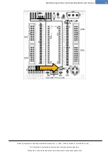
With the LED, you should pay particular
attention to the direction in which it is
mounted. In the drawings, you can
recognize the cathode (-) as the flattened
side of the LED housing. The following
markings can generally be used with
LED's to differentiate between the anode
and the cathode:
Anode (+) = the longer connection pin
Cathode (-) = the flattened side of the
housing, the larger metal surface in the
LED
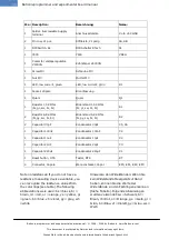
Please take the time before construction
to assign the parts supplied in the
package to the items on the package list.
This can help to avoid unnecessary
confusion and resultant problems.
Als erstes sollten sie die kleineren
Bauteile wie Widerstände und Dioden
bestücken. Danach sollten sie die IC
Fassungen und erst dann die restlichen
Teile bestücken. Achten sie bitte bei den
Dioden,
Elektrolyt-
und
Tantalkondensatoren, Transistoren und
IC's auf den polungsrichtigen Einbau.
Zudem empfehlen wir alle IC's zu
sockeln, die nötigen Sockel liegen allen
Bausätzen bei.
Den Parallelportanschluss sollten sie
zuletzt bestücken. Bei diesem Bauteil
handelt es sich um einen 25 poligen SUB-
D Stecker (männlich). Das Gerät lässt
sich also mit einem einfachen Drucker-
Verlängerungskabel anschließen.
Bei der LED sollten Sie besonders auf die
Einbaurichtung
achten.
In
den
Zeichnungen erkennen Sie die Kathode(-)
als die abgeflachte Seite vom LED
Gehäuse. Folgende Merkmale können
i.d.R. bei den LED's zur Unterscheidung
zwischen
Anode
und
Kathode
herangezogen werden:
Anode(+) = Der längere Anschlusspin
Kathode(-) = Die abgeflachte Seite vom
Gehäuse, die größere Metallfläche in der
LED
Bitte nehmen Sie sich die Zeit und ordnen
Sie die gelieferten Bauteile vor dem
Aufbau der Stückliste zu. Damit können
unnötige Verwechslungen und damit
verbundene Probleme vermieden werden.


