background image

Batronix programmer and experimental board manual – © 1998 - 2006 by Batronix, www.Batronix.com

This document is protected by German and international copyright laws. 

Dieses Werk ist durch das deutsche und internationale Urheberrecht geschützt.

24

Batronix programmer and experimental board manual

FLASH EXP.BOARD I / FLASH EXP.BOARD I

CONSTRUCTION OF A BUILDING KIT / AUFBAU EINES BAUSATZES:

You should first mount the smaller parts, 
such as resistors and diodes. Then mount 
the  IC  sockets,  and  only  then  the 
remaining  components.  When  mounting 
the  diodes,  electrolyte  and  tantalum 
condensers,  transistors  and  IC's,  please 
take care that they are placed in the right 
direction.  We  also  highly  recommend 
placing all IC's on sockets; the necessary 
sockets are included with all building kits.

IMPORTANT:  Please  mount  the  cooling 
body  to  the  voltage  regulator,  using  the 
included screw and nut, prior to soldering 
it  into  place.  Otherwise  its  pins  may  be 
soldered  in  too  deeply  and  the  cooling 
body  can  no  longer  be  mounted  to  the 
voltage regulator without difficulty.

With  the  LED,  you  should  pay  particular 
attention  to  the  direction  in  which  it  is 
mounted.  In  the  drawings,  you  can 
recognize the cathode (-) as the flattened 
side  of  the  LED  housing.  The  following 
markings  can  generally  be  used  with 
LED's  to  differentiate  between  the  anode 
and the cathode:

Anode  (+)  =  the  longer  connection  pin
Cathode  (-)  =  the  flattened  side  of  the 
housing,  the  larger  metal  surface  in  the 
LED

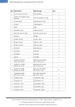
Please  take  the  time  before  construction 
to  assign  the  parts  supplied  in  the 
package to the items on the package list. 
This  can  help  to  avoid  unnecessary 
confusion and resultant problems.

Als  erstes  sollten  sie  die  kleineren 
Bauteile  wie  Widerstände  und  Dioden 
bestücken.  Danach  sollten  sie  die  IC 
Fassungen  und  erst  dann  die  restlichen 
Teile  bestücken.  Achten  sie  bitte  bei  den 
Dioden, 

Elektrolyt- 

und 

Tantalkondensatoren,  Transistoren  und 
IC's  auf  den  polungsrichtigen  Einbau. 
Zudem  empfehlen  wir  alle  IC's  zu 
sockeln,  die  nötigen  Sockel  liegen  allen 
Bausätzen bei.

WICHTIG:  Bitte  montieren  Sie  erst  den 
Kühlkörper mit der beigelegten Schraube 
samt  Mutter  an  den  Spannungsregler, 
bevor  Sie  diesen  einlöten.  Ansonsten 
kann es passieren, dass dieser mit seinen 
Pins  "zu  tief"  eingelötet  wird  und  sich 
damit  der  Kühlkörper  nicht  mehr 
problemlos  an  dem  Spannungsregler 
montieren lässt.

Bei der LED sollten Sie besonders auf die 
Einbaurichtung 

achten. 

In 

den 

Zeichnungen erkennen Sie die Kathode(-) 
als  die  abgeflachte  Seite  vom  LED 
Gehäuse.  Folgende  Merkmale  können 
i.d.R.  bei  den  LED's  zur  Unterscheidung 
zwischen 

Anode 

und 

Kathode 

herangezogen werden:

Anode(+)  =  Der  längere  Anschlusspin
Kathode(-)  =  Die  abgeflachte  Seite  vom 
Gehäuse,  die  größere  Metallfläche  in  der 
LED

Bitte nehmen Sie sich die Zeit und ordnen 
Sie  die  gelieferten  Bauteile  vor  dem 
Aufbau  der  Stückliste  zu.  Damit  können 
unnötige  Verwechslungen  und  damit 
verbundene Probleme vermieden werden.

Summary of Contents for BX32 BATUPO

Page 1: ...Programmer Experimentalboards Manual Handbuch...

Page 2: ...3 X 4 EPROM BRENNER 3 X 4 9 CONSTRUCTION OF A BUILDING KIT AUFBAU EINES BAUSATZES 9 INSTALLATION AND OPERATION INSTALLATION UND BENUTZUNG 12 CONNECTIONS ANSCHL SSE 12 CORRECT PLACEMENT OF CHIPS KORRE...

Page 3: ...ight laws Dieses Werk ist durch das deutsche und internationale Urheberrecht gesch tzt 3 Batronix programmer and experimental board manual FLASH EXP BOARD II FLASH EXP BOARD II 29 CONSTRUCTION OF A BU...

Page 4: ...s will immediately detect the device as a new USB device and display the following message on the screen Installieren Sie bitte zun chst die Prog Express Software N here Details zur Installation und H...

Page 5: ...gram Files Batronix Prog Express driver BX32P Confirm this window with Next Setzen Sie die Checkbox Folgende Quelle ebenfalls durchsuchen und klicken Sie auf den Button Durchsuchen W hlen Sie den zum...

Page 6: ...ur PC is now searching for the indicated sources and will find the programmer The software will be installed Der PC sucht nun in der angegebenen Quelle und wird das Programmierger t erkennen Die Treib...

Page 7: ...plied cable A power adapter or batteries are not required since all programming voltages between 3 and 25 volts are provided internally by a voltage generator from the USB supply voltage Der USB Ansch...

Page 8: ...o 12 volts DC plug center positive outside ground is connected it will take over the power supply to the device this can save battery power at notebooks for example Der USB Anschluss erfolgt mit dem m...

Page 9: ...e longer connection pin Cathode the flattened side of the housing the larger metal surface in the LED Please take the time before construction to assign the parts supplied in the package to the items...

Page 10: ...LED low current gr n D3 2 BC548C BC548C T2 T3 1 BC558C BC558C T1 2 Socket 14 pole Fassung 14pol 2 Socket 16 pole Fassung 16pol 1 Socket 40 pole Brennfassung 1 74HC157 74HC157 IC4 2 74HC393 74HC393 IC...

Page 11: ...resistance measuring device available you can recognize the resistance values from the color rings see table The following abbreviations were used bk black br brown rd red or orange ye yellow gr green...

Page 12: ...ctor In rare cases the address of the parallel port must be adapted to your PC The address 378 h is to be entered as the initial setting This applies to most PCs In Windows you can find the address in...

Page 13: ...device The chips have to be flush at the bottom with the marking on the chip housing pin 1 pointing in the direction of the Batronix logo If the Prog Studio 6 software shows that a chip should be plac...

Page 14: ...e longer connection pin Cathode the flattened side of the housing the larger metal surface in the LED Please take the time before construction to assign the parts supplied in the package to the items...

Page 15: ...rstand 2 2 KOhm rt rt sw br br R1 R4 2 Resistor 10 KOhm br bk bk rd br Widerstand 10 KOhm br sw sw rt br R2 R3 2 Resistor 56 KOhm gr bl bk rd br Widerstand 56 KOhm gr bl sw rt br R5 R6 3 Capacitor 1nF...

Page 16: ...1998 2006 by Batronix www Batronix com This document is protected by German and international copyright laws Dieses Werk ist durch das deutsche und internationale Urheberrecht gesch tzt 16 Batronix pr...

Page 17: ...tor In rare cases the address of the parallel port must be adapted to your PC The address 378 h is to be entered as the initial setting This applies to most PCs In Windows you can find the address in...

Page 18: ...ottom is the side facing away from the parallel port plug Pin 1 the marking on the microcontroller housing must point in the direction of the parallel port plug The upper pins of the socket remain emp...

Page 19: ...he longer connection pin Cathode the flattened side of the housing the larger metal surface in the LED Please take the time before construction to assign the parts supplied in the package to the items...

Page 20: ...13 Volt 1 1 LED low current green LED low current gr n 1 2 BC548C BC548C 2 2 Socket 14 pole Quarz 6 MHz 2 2 Socket 16 pole Fassung 14pol 2 1 Socket 40 pole Fassung 16pol 1 1 74HC157 Brennfassung 1 2 7...

Page 21: ...resistance measuring device available you can recognize the resistance values from the color rings see table The following abbreviations were used bk black br brown rd red or orange ye yellow gr green...

Page 22: ...ctor In rare cases the address of the parallel port must be adapted to your PC The address 378 h is to be entered as the initial setting This applies to most PCs In Windows you can find the address in...

Page 23: ...wrongly the component or the device may be damaged Please place the microcontroller so that pin 1 the marking on the microcontroller housing point in the direction of the labelling Flash MC Brenner I...

Page 24: ...the longer connection pin Cathode the flattened side of the housing the larger metal surface in the LED Please take the time before construction to assign the parts supplied in the package to the item...

Page 25: ...5 KOhm br gr sw br br R1 1 Resistor 6 8 KOhm bl gy sw br br Widerstand 6 8 KOhm bl gy sw br br R2 2 Capacitor 33pF Kondensator 33pF C5 C6 1 Capacitor 100nF Kondensator 100nF C2 1 Capacitor 10uF Konden...

Page 26: ...1998 2006 by Batronix www Batronix com This document is protected by German and international copyright laws Dieses Werk ist durch das deutsche und internationale Urheberrecht gesch tzt 26 Batronix pr...

Page 27: ...nnung zwischen 7 und 18 Volt sein Der max ben tigte Strom betr gt 50 mA Bitte beachten Sie unbedingt die richtige Polung der Versorgungsspannung Neben der Schraubklemme k nnen Sie die Beschriftungen V...

Page 28: ...quartz and the microcontroller input XTAL 2 can must be set here IMPORTANT If you do not use an external clock from an expansion port this switch should be turned ON The standard setting is ON Unter d...

Page 29: ...the longer connection pin Cathode the flattened side of the housing the larger metal surface in the LED Please take the time before construction to assign the parts supplied in the package to the ite...

Page 30: ...br gr sw br br R1 2 Resistor 6 8 KOhm bl gy sw br br Widerstand 6 8 KOhm bl gy sw br br R2 2 Capacitor 33pF Kondensator 33pF C5 C6 1 Capacitor 100nF Kondensator 100nF C2 1 Capacitor 10uF Kondensator...

Page 31: ...1998 2006 by Batronix www Batronix com This document is protected by German and international copyright laws Dieses Werk ist durch das deutsche und internationale Urheberrecht gesch tzt 31 Batronix pr...

Page 32: ...nnung zwischen 7 und 18 Volt sein Der max ben tigte Strom betr gt 50 mA Bitte beachten Sie unbedingt die richtige Polung der Versorgungsspannung Neben der Schraubklemme k nnen Sie die Beschriftungen V...

Page 33: ...le back and forth between operations with the internal Flash and an external memory as the program memory IMPORTANT If no external memory is connected as a program memory this switch should be turned...

Reviews: