background image

MNL-0408

June 11, 2009

Page 7

CHAPTER 2:

PLC CONTROLLED UNIT OPERATIONS

2.1

Pre-start Checks

1. Ensure that all scheduled maintenance is completed.

2. Check compressor oil level. Refer to Chapter 3. 

3. Check Emergency Stop Switch is pulled out.

2.2

Start-up Procedure

(See Figure 2-1)

1. Verify that all connections downstream of the compressor are secure.

2. Apply electric power to the unit.

3. Pull out Emergency Shop Switch.

4. Turn the Compressor Control Switch to the ON position.

2.3

Post Start Procedures 

1. Allow the compressor to build up pressure. Monitor the pressure gauge.

2. Listen to the unit as it operates. If excessive knocking or vibrations are observed shut down the unit.

3. Allow the compressor to reach full pressure.

2.4

Normal Operations

The compressor will operate automatically as needed while the Control Switch is in the ON position, 
The Emergency Stop Switch is pulled out, power is applied to the control circuit and there are no fault 
conditions.

2.5

Shutdown Procedures

1. Verify all bottle valves and fill valves are closed.

2. Turn the Compressor Control Switch to the OFF position.

3. Leave Emergency Stop Switch pulled out for at least 8 hours every 30 days to maintain the charge 

on the internal PLC battery and preserve the PLC operating memory. 

4. If the compressor is to remain idle for six months or longer, refer to the Appendix titled, Long Term 

Storage for preservation instructions.

Summary of Contents for Mini Verticus ImVT 120 II

Page 1: ...mpressors Inc Phone 757 855 6006 1328 Azalea Garden Road Fax 757 855 6224 Norfolk Virginia 23502 1944 www bauercomp com June 11 2009 1st Edition Rev 0 Chg 10 MNL 0408 2009 Bauer Compressors Inc Mini Verticus High Pressure Air Compressor Unit ImVT 120 II AP ...

Page 2: ...nal or a complete rewriting of the entire Manual A Revision occurs whenever a complete Section or Appendix is rewritten or added A Change occurs when individual pages drawings or tables are changed WARNING This Instruction Manual and Replacement Parts List contains safety information and instructions for the ImVT 120 II Mini Verticus High Pressure Air Compressor Unit You must read understand and f...

Page 3: ...IC PANEL COMPONENTS 8 2 6 1 Emergency Stop Switch 8 2 6 2 Starter Reset 8 2 6 3 Compressor Control Switch 9 2 6 3 1 2 Position Standard 9 2 6 4 Indicator Lamps 9 2 6 4 1 PLC Warning and Alarm Lamps 9 2 6 4 1 1 Warning Lamp Amber 9 2 6 4 1 2 Alarm Lamp Red 9 2 6 5 Hourmeter 9 2 6 6 PLC Control 9 2 7 WARNINGS 9 2 7 1 One Flash Final Separator Warning 9 2 7 2 Two Flashes Securus Monitor Optional 10 2...

Page 4: ...tage Valves 22 3 1 9 4 1 Removing the Valves of the 2nd Stage 22 3 1 9 4 2 Reassembling the Valves of the 2nd Stage 23 3 1 9 5 IK120 II 3rd Stage Valves 24 3 1 9 5 1 Removing the Valves of the 3rd Stage 24 3 1 9 5 2 Reassembling the Valves of the 3rd Stage 25 3 1 10 Replacement Parts List 26 3 1 11 Troubleshooting 44 3 1 11 1 Troubleshooting Table 44 3 2 THREE STAGE AUTOMATIC CONDENSATE DRAIN SYST...

Page 5: ...5 3 9 Securus Electronic Moisture Monitor System 61 5 3 9 1 Securus Cartridge 61 5 3 9 2 Securus Indicator 61 5 4 MAINTENANCE 62 5 4 1 Oil and Water Separator 62 5 4 2 Cartridge Replacement 63 5 4 2 1 Leaking at the Safety Bore 64 5 5 REPLACEMENT PARTS LIST 65 CHAPTER 6 COMPRESSOR UNIT DRIVE 6 1 VERTICAL SELF TENSIONING 70 6 2 MAINTENANCE OF THE V BELT AND SHEAVES 70 6 2 1 Check the Flywheel and S...

Page 6: ...G A NEW PROGRAM 84 7 7 1 Installing a new program using an EEPROM cartridge 85 7 8 OVERRUN TIMER 86 7 8 1 Adjusting the Overrun Timer 86 7 9 WIRE HARNESS CONNECTIONS 87 7 10 REPLACEMENT PARTS LIST 88 7 11 TROUBLE SHOOTING GUIDE 89 7 11 1 Compressor Will Not Start 89 7 11 2 Compressor Is Shutdown Alarm Code Flashing Sequence 89 7 11 2 1 One Flash Compressor High Temperature 89 7 11 2 2 Two Flashes ...

Page 7: ... 2 Indoor Installation 105 9 2 2 2 3 Natural Ventilation 105 9 2 2 2 4 Forced Ventilation 106 9 2 2 3 Electrical Installation 106 9 2 2 3 1 Electric Drive 106 9 2 2 3 2 Electrical Supply 106 9 3 LONG TERM STORAGE 109 9 3 1 General 109 9 3 2 Preparations 109 9 3 2 1 Units Equipped with a Filter System 109 9 3 3 Preserving the Compressor 109 9 3 4 Preventive Maintenance During Storage 110 9 3 5 Lubr...

Page 8: ... Figure 3 12 IK120 II 1st Stage Valve 21 Figure 3 13 IK120 II 2nd Stage Valves 22 Figure 3 14 Using the Special Tool P N 082048 23 Figure 3 15 Securing the Intake Valve 23 Figure 3 16 IK120 II 3rd Stage Valves 24 Figure 3 17 Removing the 3rd Stage Pressure Valve 25 Figure 3 18 Crankcase Assembly 26 Figure 3 19 Piston and Cylinder 1st Stage IK120 II 28 Figure 3 20 Piston and Cylinder 2nd Stage 29 F...

Page 9: ... 5 10 P2S Purification System 65 Figure 5 11 Oil and Water Separator 66 Figure 5 12 Securus Electronic Moisture Monitor System 68 CHAPTER 6 COMPRESSOR UNIT DRIVE Figure 6 1 Vertical Motor Mount typical 70 CHAPTER 7 ELECTRICAL PANEL ASSEMBLY Figure 7 1 Electrical Panel Assembly 71 Figure 7 2 Electrical Panel Label 73 Figure 7 3 Transformer and Fuses 73 Figure 7 4 Motor Starter and Overload Relay 74...

Page 10: ... CONTROLS Figure 8 1 Pressure Maintaining Valve 94 Figure 8 2 Safety Valve 95 Figure 8 3 Digital Pressure Switch 96 Figure 8 4 Switches and Valves 99 CHAPTER 9 APPENDIX Figure 9 1 Lifting Devices 103 Figure 9 2 Incoming Power Wiring Label 107 Figure 9 3 6 Bolt and 4 Bolt Torque Sequence 115 ...

Page 11: ...or any inaccuracies or the con sequences thereof 1 1 1 Manual Safety Notices Important instructions concerning the endangerment of personnel technical safety or operator safety will be specially emphasized in this manual by placing the information in the following types of safety notices DANGER DANGER indicates an imminently hazardous situation which if not avoided will result in death or seri ous...

Page 12: ...dicate the number of operating hours when the part is to be replaced a replaced every 1 000 hours b replaced every 2 000 hours and c replaced every 4 000 hours NS in the Item Number column indicates the part is not illustrated but is available When placing an order for spare parts please provide the following information to ensure delivery of the correct parts The model number date of manufacture ...

Page 13: ...torage over 90 days of this product Reproducible Forms Reference Data Torque Values Torque Sequence Conversion Formulas Approved Lubricants Glossary of Abbreviations Acronyms Additional Documents WARNING The use of repair parts other than those included in the Bauer Replacement Parts Lists may create unsafe conditions over which Bauer has no control Such unsafe conditions can lead to accidents tha...

Page 14: ...ressure hourmeter and a P2 purification sys tem with Securus moisture monitoring system The approximate weight of the ImVT 120 II Mini Ver ticus compressors is 700 to 750 lbs 1 4 1 Compressor Unit Major Assemblies The compressor unit is comprised of the following major assemblies Compressor Block Drive Motor Base and Frame Assembly Automatic Condensate Drain System Electric Control System Enclosur...

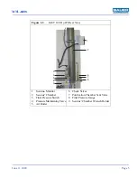
Page 15: ... 120 II AP Rear View 1 Securus Monitor 2 Securus Chamber 3 Final Pressure Switch 4 Pressure Maintaining Valve 5 Air Outlet 6 Check Valves 7 Purification Chamber Vent Valve 8 Final Pressure Gauge 9 Securus Chamber Wrench Holder 1 2 3 4 5 6 9 6 7 8 ...

Page 16: ... 1st stage 87 102 psig 6 7 bar Safety valve setting 1st stage 131 psig 9 bar Intermediate pressure 2nd stage 464 711 psig 40 49 bar Safety valve setting 2nd stage 870 psig 60 bar Direction of rotation when facing flywheel CCW Compressor speed 1 385 RPM Oil capacity 2 96 qts 2 8 liters Oil Pressure 58 87 psig 4 6 bar Recommended oil BAUER OIL 0024 Maximum Inclination 10 in all directions 1 5 2 Comp...

Page 17: ...erates If excessive knocking or vibrations are observed shut down the unit 3 Allow the compressor to reach full pressure 2 4 Normal Operations The compressor will operate automatically as needed while the Control Switch is in the ON position The Emergency Stop Switch is pulled out power is applied to the control circuit and there are no fault conditions 2 5 Shutdown Procedures 1 Verify all bottle ...

Page 18: ...n tained by a internal battery in the PLC Removing all power from the compressor will allow the battery to discharge over a 30 day period To recharge the PLC battery apply power to the unit put the Control Switch in the OFF position pull out the Emergency Stop Switch and allow the battery to charge for at least 8 hours every 30 days 2 6 2 Starter Reset The Starter Reset is a blue push button with ...

Page 19: ...This panel will be controlled with a Telemecanique 16 I O Twido Programmable Logic Controller This unit will provide logical operations to the overall system that includes the high pressure compressor purification systems and other accessories 2 7 Warnings The amber Warning Lamp located on the control panel flashes warning codes with a 0 5 second on 0 5 second off sequence with a distinct pause be...

Page 20: ...e compressor will shutdown the I1 lamp will extinguish and the alarm code will flash 2 8 2 Two Flashes Compressor Low Oil Pressure The compressor oil pressure switch is located on the back of the compressor block mounted with the oil pressure gauge The switch is N O Normally Open and is connected to the PLC on terminal I2 During startup of the compressor the oil pressure switch is bypassed for a p...

Page 21: ... Bauer Compressors for making arrangements to replace the separator When the Alarm level has been achieved the compressor will no longer function and will require the replace ment of the separator Once this is accomplished the unit can be re activated by making adjustments to the PLC Please contact Bauer Product Support for detailed instructions 2 8 7 Seven Flashes Condensate Fault OPT The optiona...

Page 22: ... in the center 2nd stage on the right and 3rd stage on the left looking from the filter side The compressor block are particularly suitable for continu ous operation because of it s rugged design and corrosion resistant intermediate filter and cooler assem blies 3 1 2 Component Location Figure 3 1 IK120 II Compressor Block 1 1st Stage Cylinder 2 Intake Filter 3 Oil Filler Neck 4 3rd Stage Cylinder...

Page 23: ...which may be a factory installed option 3 1 4 Compressor Lubrication 3 1 4 1 Description Refer to Figure 3 3 The compressor is provided with forced feed lubrication The oil pressure is pro duced by a low speed gear pump 1 The oil pressure is approximately 73 psi 5 bar The oil pump 1 is coupled to and driven by the crankshaft It pumps oil through the oil line filter 2 and a minimum pressure valve 3...

Page 24: ...ntenance of the compressor using the correct oil is of vital importance Due to the thermal load on the compressor only high quality oil should be used You are recommended to restrict oils to those which have been approved by us and are listed in the compressor block specifica tions found in Chapter 1 Figure 3 3 Lubrication Oil Circuit 1 Oil Pump 2 Oil Filter 3 Minimum Pressure Valve 4 Guide Piston...

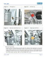
Page 25: ...n the minimum and maximum notches Oil level must never be below the minimum mark as this will cause severe damage due to lack of lubrication Oil level must also not exceed the maximum mark as this will cause excessive lubrica tion of the compressor and may result in a carbon buildup on the valves Figure 3 4 Oil Sight Glass Figure 3 5 Oil Filler Cap Figure 3 6 Removing the Oil Filter Cover Figure 3...

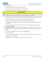
Page 26: ...ew minutes and adjust the oil level if necessary before putting the unit into operation 3 1 5 Venting the Oil Pump Venting of the Oil Pump may be necessary if after maintenance work oil pressure is low or not built up after starting the unit or if the unit should have been running backwards because of a wrong phase sequence 1 Open all the condensate drain valves to avoid building up pressure 2 Sta...

Page 27: ... changed at regular intervals See the Maintenance Schedule for the recom mended interval 1 Unscrew and remove Knurled Nut 1 2 Remove Washer 2 and Filter Housing 3 3 Discard Filter Element 4 and replace with new Filter Element Bauer Part Number N25950 4 Reassemble in reverse order Figure 3 8 Intake Filter 1 Knurled Nut 2 Washer 3 Filter Housing 4 Filter Element 1 2 3 4 ...

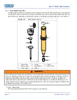
Page 28: ... Separator 1 Vortex Plate 2 Hollow Screw 3 Center Insert 4 O ring 5 Knurled Nut 6 Gasket 7 Fitting 8 Safety Valve WARNING The rapid depressurizing and repressurizing of the intermediate separator during condensate draining sub jects it to metallurgical stresses To prevent catastrophic failure with the possibility of damage injury or death the intermediate separator must be replaced after 85 000 lo...

Page 29: ...alves and Heads 3 1 9 1 Functional Description The valve heads of the individual stages form the top part of the cylinders See Figure 3 10 The intake and pressure valves are fitted inside the valve heads Note that the valves are operated by the flow of the medium On the intake stroke the intake valves open and the medium flows into the cylin ders At the start of the pressure stroke the intake valv...

Page 30: ...ork on the valves turn the compressor manually using the flywheel and check whether all items have been correctly installed 30 minutes after restarting the compressor stop the unit let it cool down to ambient temperature and retighten valve studs and cap nuts Otherwise the gasket set may cause a leak Remove and check the valves every 1000 operating hours Replace the valves every 2000 operating hou...

Page 31: ...MNL 0408 June 11 2009 Page 21 Figure 3 12 IK120 II 1st Stage Valve 1 Plate Valve 2 Valve Head 3 Washer 4 Hex Head Screw 5 Hex Head Screw 6 Washer 7 O ring 1 2 3 4 5 6 7 ...

Page 32: ...ecure them in a vise with the valve head on top 4 Using the special tool provided with the unit remove the intake valve 6 See Figure 3 14 5 Turn the valve head over and replace it on the metal pins 6 Remove the cap nut 1 7 Unscrew the stud 2 approximately five turns 8 Remove the pressure plug 3 and take out the valve parts 9 Clean the intake and pressure valves and check for wear 10 Clean and chec...

Page 33: ...re the intake valve as follows See Figure 3 17 Peen the valve head aluminum over the screw in thread of the intake valve in two places opposite one another Use a small drift pin approximately 5mm in diameter 4 Insert the O ring 4 and the pressure valve parts 5 Figure 3 14 Using the Special Tool P N 082048 Figure 3 15 Securing the Intake Valve CAUTION In order to avoid damaging the special tool or ...

Page 34: ...Valves of the 3rd Stage 1 Remove the intake and pressure lines from the valve head 2 2 Remove the cap nut 8 and loosen stud 6 three or four turns 3 Remove the screws 9 holding the valve head onto the cylinder and take off valve head cover 5 4 Remove the 3rd stage pressure valve by putting two screwdrivers into the removal groove of the pressure valve body See Figure 3 17 It may be necessary to loo...

Page 35: ...ly by blowing compressed air through the valve in the direction of flow 3 Secure the intake valve as follows See Figure 3 17 Peen the valve head aluminum over the screw in thread of the intake valve in two places opposite one another Use a small drift pin approximately 5mm in diameter 4 Reinstall the pressure valve 4 by putting O ring 3 into valve head 2 Check it for abrasions 5 Insert pressure va...

Page 36: ...nkcase 2 1 083399 Crankshaft complete IK120 II 3 1 N2638 Roller Bearing 4 2 N2635 Circlip 5 1 66209 Bearing Cap 6 1 N15406 Roller Bearing 7 1 N15265 O ring 8 1 66684 Cover 9 1 N170 Shaft Seal 10 1 N3745 O ring 11 1 61054 Plug 12 1 N15412 O ring Figure 3 18 Crankcase Assembly 1 2 3 4 4 5 6 7 8 9 10 11 12 13 14 15 16 17 18 19 20 21 23 24 19 25 26 27 28 22 22 16 29 30 ...

Page 37: ... 0020 Allen Screw 16 8 WAS 0021 Washer 17 a 2 N4261 Gasket 18 2 PLU 0040 Plug 19 2 N25475 Oil Sight Gauge 20 1 N1316 Gasket 21 1 N4570 Plug 22 2 78038 Support 23 4 WAS 0030 Spring Washer 24 4 NUT 0076 Hex Nut 25 4 WAS 0031 Washer 26 4 N350 Hex Head Screw 27 6 SCR 0113 Hex Head Screw 28 3 N16126 Countersunk Screw 29 1 N2375 Coupling 30 1 N25638 Ball Valve ...

Page 38: ...nder Assembly IK120 II 1 1 080734 Cylinder IK120 II 2 c 1 N4654 O ring 3 1 069975 Piston Assembly Items 3 61Piston 4 2 N484 Circlip 5 1 N802 Piston Pin 6 1 N1787 Piston Ring Set 7 4 N215 Stud 8 4 WAS 0021 Washer 9 c 4 NUT 0119 Self Locking Hex Nut Figure 3 19 Piston and Cylinder 1st Stage IK120 II 1 2 3 4 4 5 7 8 9 6 ...

Page 39: ...063 O ring 3 1 080383 Guide Cylinder 4 c 1 N2640 O ring 5 4 NUT 0119 Self Locking Hex Nut 6 4 WAS 0021 Washer 7 4 N2790 Stud 1 072249 Piston Assembly Complete Items 8 11 8 1 062487 Piston 9 2 N484 Circlip 10 1 N1429 Piston Pin 11 1 N2647 Piston Ring Set Figure 3 20 Piston and Cylinder 2nd Stage 1 2 3 4 5 6 7 8 9 9 10 11 ...

Page 40: ...68 O ring 3 1 082480 Cylinder 4 c 1 N7063 O ring 5 1 083404 Guide Cylinder 6 c 4 NUT 0119 Self Locking Hex Nut 7 4 WAS 0021 Washer 8 4 N2790 Stud 9 c 1 N2640 O ring 10 1 072165 Guide Piston Assembly Items 11 13 11 Guide Piston Available only with 072165 12 Piston Pin Available only with 072165 13 2 N484 Circlip Figure 3 21 Piston and Cylinder 3rd Stage 1 2 3 4 5 6 7 8 9 10 11 12 13 ...

Page 41: ...ty Part No Description Notes 1 078043 Piston and Sleeve Assembly 1 Piston Available only with 078043 2 a 1 N23755 O ring 3 Piston Liner Available only with 078043 4 1 N25376 Piston Ring Set Figure 3 22 Piston and Sleeve 3rd Stage 1 2 3 4 ...

Page 42: ...ption Notes 1 080688 1st Stage Valve Head Assembly IK120II 1 b 1 N26531 Plate Valve IK120 II 2 1 080677 Valve Head IK120 II 3 6 Washer 4 6 N1262 Allen Screw 5 1 N28108 Allen Screw 6 1 WAS 0021 Washer 7 1 N1539 O ring Figure 3 23 1st Stage Valve Head and Valve IK120 II 1 2 3 4 5 6 7 ...

Page 43: ...1 2 3 4 5 9 8 6 10 7 This page is inserted to provide proper page sequencing ...

Page 44: ...th 012841 4 Spring Available only with 012841 5 Valve Plate Available only with 012841 6 Valve Seat Available only with 012841 7 a 2 240 Gasket 8 1 014582 Pressure Valve Assembly Items 9 15 20 9 b 1 012835 Pressure Valve Insert Items 10 14 10 Valve Seat Available only with 012835 11 Valve Plate Available only with 012835 12 1 1026 Spring Figure 3 24 2nd Stage Valves and Valve Head 19 17 16 14 9 3 ...

Page 45: ...d Stage Valves and Valve Head KIT Qty Part No Description Notes 13 Valve Insert Available only with 012835 14 a 1 N3521 O ring 15 1 14332 Spring Washer 16 1 14124 Coupling 17 b 1 71064 Stud 18 a 1 N380 Gasket 19 1 N84 Cap Nut 20 6 SCR 0180 Allen Screw ...

Page 46: ...096 Valve Head Assembly 1 b 1 081409 Intake Valve 2 1 082087 Valve Head 3 1 N2789 O ring 4 b 1 014121 Discharge Valve 5 1 082086 Valve Head Cover 6 b 1 N3738 Stud 7 a 1 N3625 Gasket 8 1 N3589 Acorn Nut 9 6 N17730 Screw 10 6 N58 Washer Figure 3 25 3rd Stage Valves and Valve Head 1 2 3 4 5 6 7 8 9 10 ...

Page 47: ... Description Notes 1 082552 Flywheel Assembly 1 1 N1386 Feather Key 2 1 082553 Fanwheel Hub 3 1 080975 Washer 4 1 N176 Spring Washer 5 4 N26666 Screw 6 1 082496 Fanwheel 7 4 N108 Spring Washer 8 4 N19548 Screw Figure 3 26 Flywheel 1 2 3 4 5 6 7 8 ...

Page 48: ...scription Notes 1 081799 Intermediate Separator Assembly 1 1 81148 Plate 2 1 81643 Hollow Screw 3 1 76613 Inset Assembly 4 1 N3556 O ring 5 1 13937 Knurled Ring 6 1 N1316 Gasket 7 1 N20215 Fitting 8 Safety Valve See Figure 3 29 Figure 3 27 Intermediate Separator 1 2 3 4 5 6 7 8 ...

Page 49: ...iption Notes 1 079577 Intake Filter Assembly 1 1 N4870 Knurled Nut 2 1 N3313 Washer 3 1 79574 Filter Housing Front 4 a 1 N25950 Filter Element 5 1 79575 Filter Housing Back 6 1 N19502 Hex Head Bolt 7 1 N3374 Clamp Figure 3 28 Intake Filter 1 2 3 4 5 6 7 ...

Page 50: ...tage 3 1 070724 Aftercooler 4 1 078200 Fanwheel Guard 5 1 081802 Safety Valve 1st Stage 6 1 072935 Safety Valve 2nd Stage 7 8 062773 Mounting Bracket 8 8 WAS 0024 Washer 9 8 NUT 0118 Self Locking Hex Nut 10 8 N3494 Stud 11 4 N20059 Fitting Figure 3 29 IK120 II Cooling System 29 28 4 27 26 3 32 33 20 12 13 25 24 12 12 11 21 22 23 12 13 14 15 6 1 12 11 12 13 5 16 17 18 12 19 11 19 12 2 10 8 9 7 31 3...

Page 51: ...ap 16 1 N20327 Tee 17 1 N15175 Plug 18 1 N7433 Cap 19 2 N26751 Coupling 20 1 N20183 Connector 21 2 77894 Clamp 22 2 N2460 Washer 23 2 SCR 0020 Allen Screw 24 1 N52 Plug 25 1 78197 Tubing Assembly 26 3 78199 Stud 27 3 11887 Mounting Bracket 28 3 WAS 0021 Washer 29 3 NUT 0119 Self Locking Hex Nut 30 1 N20310 Fitting 31 1 083454 Tubing Assembly 32 1 71148 Fitting 33 1 56983 Gasket ...

Page 52: ... Oil Filter Cover 2 1 N4058 O ring 3 1 N25327 O ring 4 1 77774 Rubber Gasket 5 a 1 N25326 Filter Element 6 1 77878 Cover Plate 7 2 N25328 Allen Screw 8 2 N2889 Gasket 9 1 78421 Gasket 10 1 N24585 Gear Pump 11 2 RNG 0070 O ring 12 2 N19506 Hex Head Screw Figure 3 30 Lubrication System Assembly 1 2 3 4 5 6 7 8 9 10 11 12 13 14 15 15 15 16 16 16 17 17 18 ...

Page 53: ... 43 Figure 3 30 cont Lubrication System Assembly KIT Qty Part No Description Notes 13 2 WAS 0021 Washer 14 1 077970 Regulating Valve 15 4 N1316 Gasket 16 3 N52 Plug 17 1 076757 Connecting Tube Assembly 18 1 N2037 Male Connector ...

Page 54: ...alve 3 Replace 4 Replace 5 Tighten Safety valves between stages releasing pressure 1 Intermediate pressure too high 2 Valves not closing properly 1 Service and clean valves 2 Service and clean valves Compressor running too hot 1 Insufficient supply of cool ing air 2 Intake or outlet valve not closing properly 3 Wrong direction of rotation 1 Check location for adequate ventilation 2 Check and clean...

Page 55: ...ndensate manifold A condensate collection system The automatic condensate drain system drains the intermediate separator and the oil and water separa tor every 15 minutes during operation Additionally the automatic condensate drain system unloads the compressor during the starting phase and drains these filters at shutdown of the compressor unit Figure 3 31 Automatic Condensate Drain 1 Solenoid Va...

Page 56: ...ve 4 3 2 1 2 Condensate Drain Every 15 minutes the timer deenergizes the solenoid valve 1 for approximately 10 seconds The sole noid valve 1 opens and drains the condensation from the intermediate separator 2 This causes a pressure loss in the intermediate separator and the control air for the condensate drain valve 4 As the pressure of the control air is dropping the piston of the condensate drai...

Page 57: ...her 2 Observe the drainage of condensation a If the system drains more than 2 ounces of liquid per stage either the system or the corresponding condensate drain valve is not working properly b Find the fault and remedy accordingly 3 If little or no condensation emerges the automatic system is operating properly 4 The condensate collection tank should be emptied regularly Due care must be taken to ...

Page 58: ... only 1 1 N27288 Solenoid Coil 115 VAC 50 60 Hz 2 1 N27099 Solenoid Valve 3 1 N01028 Copper Gasket 4 1 RED 0058 Reducer Bushing 5 2 N01316 Copper Gasket 6 1 CON 0061 Male Connector 7 1 PLU 0004 Plug 8 1 070615 Male Connector w Nozzle 9 1 064009 Condensate Drain Valve 10 1 GKT 0016 Copper Gasket 11 1 CON 0143 Male Connector Figure 3 33 ACD System 4 3 1 5 2 9 10 11 8 6 7 ...

Page 59: ...ng Plate 2 2 N00638 O ring 3 1 MFD 0035 ACD Manifold 4 2 N00829 Socket Head Cap Screw 5 2 N03625 Copper Gasket 6 1 Elbow 7 1 Connecting Tube 8 1 Female Connector 9 1 N02507 O ring 10 1 064004 Valve Connection 11 1 N02320 O ring Figure 3 34 ACD Manifold Assembly 1 2 3 4 5 6 7 8 9 10 11 ...

Page 60: ... No Description Notes 1 064009 Condensate Drain Valve Assembly 1 1 064000 Top Flange 2 1 N16269 Seal Ring 3 1 064003 Valve Piston 4 1 N00638 O ring 5 1 N04881 O ring 6 1 064001 Valve Body Figure 3 35 Condensate Drain Valve Assembly 1 2 3 4 5 6 7 8 9 10 11 14 13 15 15 12 16 ...

Page 61: ...ty Part No Description Notes 7 1 N2507 O ring 8 1 064005 Valve Seat 9 1 N04496 O ring 10 1 064002 Base Flange 11 1 064498 Condensate Drain Tap Seat 12 1 065500 Condensate Drain Tap 13 1 N16334 Banjo Fitting 14 AR TUB R 0038 Tubing 15 8 SCR 0150 Socket Head Cap Screw 16 1 067458 Tool Set ...

Page 62: ...ater is not possible through simple methods therefore the condensate has to be completely removed It is most practical to collect this condensate in special containers and dispose of it entirely For these compressor units a metal housing and tank assembly is used A float level switch is also included The condensate is drained from the tank assembly by the manual drain valve into a separate contain...

Page 63: ...te Collector Cover 2 1 GKT 0050 Gasket 3 2 ELM 0160 Fine Filter Element 4 2 ELM 0161 Coarse Filter Element 5 1 HUS 0050 Condensate Collector 6 1 SWT 0265 Float Switch 7 1 TNK 0092 Condensate Collection Tank 8 1 VAL 0386 Manual Drain Valve 9 1 PLU 0011 Plug 10 1 MFD 0035 ACD Manifold Figure 3 37 Condensate Collector 1 2 3 4 5 6 7 8 9 10 ...

Page 64: ...perate unit to final pressure and check final pressure switch hour after maintenance work Check screws and fittings for tightness 500 operating hours Service micronic intake filter Check all connections for leakage 1 000 operating hours Valve Check 2 000 operating hours Change Synthetic Oil and Change Oil Filter Replace Valves 3 000 operating hours Check pistons and piston rings Annually Check ope...

Page 65: ...aintain a pressure of 700 to 1 100 psi 50 to 80 bar within the system to prevent moisture from entering the compressor and air pro cessing system 5 1 2 Chamber Safety Bore The chambers in all Bauer air processing systems are designed to prevent pressurization if the cartridge is missing not seated properly or damaged See Figure 5 1 Without a cartridge properly in place the safety bore is not seale...

Page 66: ...ial number can be found on the compressor unit identifi cation plate in the main electrical enclosure and frame 5 1 4 2 Purification System Dataplate Refer to the compressor unit purification system dataplate See Figure 5 2 on the compressor front to determine your air processing system model and specifications 5 1 4 3 Cartridge Installation Dataplate The function performed by each chamber in the ...

Page 67: ...MNL 0408 June 11 2009 Page 57 5 1 4 4 Air Processing Cartridge Operating Hours Form Date Operating hours Ambient temp during compression Correction factor Adjusted cartridge hours Today Total ...

Page 68: ...rus Elec tronic Moisture Monitor System Purification Chamber Figure 5 3 shows the functional interconnection of all the components A Securus Indicator and associated wiring are also added Figure 5 3 P2S Purification System 1 Oil and Water Separator 2 Check Valves 3 Bleed Valves 4 Pressure Maintaining Valve 5 Purification Chamber 6 Securus Indicator 7 Safety Valve OUT IN 1 2 2 3 3 4 5 7 6 ...

Page 69: ... jects it to metallurgical stresses To prevent catastrophic failure with the possibility of damage injury or death the oil and water separator P N 079416 must be replaced after a predetermined number of cycles One load cycle equals one pressurization plus one depressurization Units operating between 3 000 and 5 000 psi 130 000 load cycles 32 500 hours of operation Units operating between 5 000 and...

Page 70: ...ruction The cartridge casing top and bottom are aluminum and are packed with one or more of the following 1 A catalyst to convert carbon monoxide to carbon dioxide 2 Activated carbon which absorbs oil vapors effecting taste and odor 3 Molecular sieve to absorb oil and water 5 3 3 2 Cartridge Handling 1 Never open the protective packaging a cartridge comes in prior to its actual use The highly sens...

Page 71: ...acts as the safety valve for the final stage of the compressor 5 3 9 Securus Electronic Moisture Monitor System The Securus Electronic Moisture Monitor System is a factory installed option which warns the opera tor in advance of expiration of the life of the cartridges The Securus Indicator receives signals con cerning the condition of the drying agent inside the Securus cartridge from the attache...

Page 72: ...ate the threads and O rings as well as the threaded part of the sintered metal filter with petro leum jelly Apply sparingly 9 Dry the inside of the filter housing with a clean cloth and check for corrosion before reinstalling the sintered metal filter 10 In the event you discover corrosion replace the corroded parts with new BAUER parts 11 Reinstall the sintered metal filter assembly and filter he...

Page 73: ... Figure 5 9 1 Disconnect the power and shut off the inlet supply line if applicable 2 Depressurize the system by means of the bleed valve Figure 5 7 Oil and Water Separator Figure 5 8 Sintered Metal Filter Assembly 1 Filter Head 2 Sintered Metal Filter 3 Center Screw 4 O rings Figure 5 9 Cartridge Replacement 1 2 3 4 ...

Page 74: ...ll the new cartridge Be sure the cartridge snaps into place 10 Reinstall the chamber head 11 Close the bleed valve restore the power and reconnect the inlet supply line if applicable 5 4 2 1 Leaking at the Safety Bore 1 Remove the cartridge following steps 1 to 4 in Paragraph 5 4 2 2 Install cartridge if missing 3 Remove cartridge and inspect O rings 4 Replace O rings if necessary 5 Ensure protect...

Page 75: ...Oil and Water Separator See Figure 5 11 2 2 VAL 0007 Check Valves 3 2 VAL 0377 Bleed Valve 4 1 VAL 0053 Pressure Maintaining Valve 5 1 080145 Securus Chamber See Figure 5 12 6 1 N15095 Securus Indicator See Figure 5 12 7 1 VAL 0169 Safety Valve Figure 5 10 P2S Purification System OUT IN 1 2 2 3 3 4 5 7 6 ...

Page 76: ...ption Notes 1 079416 Oil and Water Separator Assembly 1 Separator Head Available only with 079416 2 2 N04586 O Ring 3 1 061860 Sintered Metal Filter 4 Separator Housing Available only with 079416 5 Bottom Plug Available only with 079416 Figure 5 11 Oil and Water Separator 1 2 3 4 5 2 ...

Page 77: ...1 2 3 4 5 9 8 6 10 7 This page is inserted to provide proper page sequencing ...

Page 78: ...04736 Backup Ring 3 2 N04735 O ring 4 1 060037 Securus Cartridge 5 Filter Body Available only with 80145 6 1 ADP 0204 Adapter Right Angle 7 1 059850 Socket RF type 8 2 012293 Tool Post Screw 9 1 06135 Cover Plate 10 Filter Head Available only with 80145 11 1 059855 Nut Figure 5 12 Securus Electronic Moisture Monitor System 1 2 3 4 5 3 2 9 6 7 8 10 11 12 13 14 15 16 17 18 ...

Page 79: ...onic Moisture Monitor System Item Qty Part No Description Notes 12 1 059852 Drawback Screw 13 1 059854 Loose Pin 14 1 060062 Compression Spring 15 1 059853 Fixed Pin 16 1 059851 Bolt 17 1 002181 Compression Spring 18 1 N15095 Securus Indicator 110 120VAC 50 60 Hz ...

Page 80: ...rty or rusty sheave impairs the drive s efficiency and abrades the cover of the belt which results in premature failure A worn sheave shorten belt life as much as 50 If the groove is worn to the point where the belt bottoms slippage may result and the belts may burn If the side walls are dished out the bottom shoulder ruins the belt prematurely by wearing off the bottom corners 6 2 2 Check the V b...

Page 81: ...re incorporated into a pro prietary program permanently saved into PLC memory using EEPROM technology There are normally six PLC programs used in this Electrical Panel Assembly based on the pressure and use of the com pressor The program version used can be identified by the white sticker on the face of the PLC The panel is pre wired and fused for the horsepower and voltage of the compressor Activ...

Page 82: ...t the operator to replace the high pressure purification cartridges The Carbon Monoxide Monitor is used to continuously sample the air that is compressed for use in the system Again the unit will alarm and shut down the compressor if unsafe levels are detected The Carbon Monoxide Monitor also comes with a Calibration Kit to ensure accurate readings are being taken The Condensate High Level Alarm w...

Page 83: ...ds 120 VAC single phase panel loads are as follows AC Power Available Light Negligible Warning Alarm lights Negligible ACD coils up to 4 35 W each maximum with 3 max energized Motor Starter coil max 26 0 VA sealed max CO Monitor Solenoid valve 8 W CO Monitor power 0 9 W Securus Electronic Moisture Monitor System 20 4 VA PLC Controller 22 0 VA Figure 7 2 Electrical Panel Label Figure 7 3 Transforme...

Page 84: ...l voltage is 120 VAC The 3 phase 460 volt motor starter part number SRT 0196 will support up to 32 Amps con tinuous The coil within the starter can be replaced with part number COI 0017 7 4 2 Overload Relay The overload relay provides thermal overload protection The overload relay used on the 460 V 7 5 HP 3 phase assembly is RLY 0138 The relay must be set to match the motor s Full Load Amps Refer ...

Page 85: ...ompressor will allow the battery to discharge over a 30 day period Apply power to the unit by pulling out the Emergency Stop Switch and leave on for at least 8 hours every 30 days 7 4 4 Starter Reset There is a blue 22mm push button on the door of the electrical enclosure with the letter R at its center Pushing this button will reset the thermal overload relay on the motor starter Should the elect...

Page 86: ...he ON position to operate the compressor system When posi tioning the switch to the ON position it will illuminate Green The compressor will start and stop auto matically based on the status of the pressure switch CONTINUOUS This switch position maintained will allow the compressor to build up to final pres sure then will activate an unloading valve When demand is re established the unloading valv...

Page 87: ...side of the bottom row and indicate the following a PWR The supply voltage to the PLC is correct b RUN On when the program is running Flashes when program execution is stopped c ERR Illuminates red on application fault d STAT Indicates the status of an application variable Figure 7 6 PLC CNT 0052 Figure 7 7 Status Lights Inputs Outputs Status Lights Program Version 120 VAC Supply IN OUT 0 1 2 3 4 ...

Page 88: ... The power supply physically exists inside the PLC All PLC outputs are of a relay type and are powered through the control transformer supplying 120 VAC single phase to the various loads Please refer to unit schematic for the as built specifications Table 7 1 PLC Program Versions Description 5 000 psi 6 000 psi Breathing Air Compressor without Unloader v2 45 v2 35 Industrial Compressor Unit with U...

Page 89: ...flect the following values when it is built When the warning is illuminated the unit will still continue to function properly but will prompt the operator to contact Bauer Compressors for making arrangements to replace the separator When the Alarm level has been achieved the compressor will no longer function and will require the replace ment of the separator When this is accomplished the unit can...

Page 90: ...normally the I7 lamp will illuminate and the warning shows on the LCD Display This warning is meant to prompt the operator to schedule replacement of the purification cartridges in the near future The Warning relay is wired normally open The relay is wired into a wire harness using the Black Orange and Violet Orange color wires Refer to unit schematic for additional information Under nor mal opera...

Page 91: ...he oil pressure has sta bilized the switch should be closed Should the compressor lose oil pressure then the compressor will shutdown the I2 lamp will extinguish and the alarm code will flash 7 6 3 Three Flashes Compressor Overrun Timer The compressor has an overtime function where if the compressor runs continuously for 5 hours then the compressor will shutdown and the alarm code will flash This ...

Page 92: ...to a wire harness using the White Black and Red White color wires Refer to unit schematic for additional information Under normal operat ing conditions the relay is open and the I4 lamp on the PLC is off On a CO ALARM condition the compressor will shutdown the I4 lamp will be illuminated and the alarm code will flash 7 6 6 Six Flashes Final Separator Shutdown The high pressure breathing compressor...

Page 93: ...arator The switch is N O Normally Open and is connected to the PLC on terminal I6 The switch is wired into a wire harness using the Grey and Pink color wires Refer to unit schematic for additional information Under normal operating conditions the switch is open and the I6 lamp on the PLC is off On a high condensate condition the compressor will shutdown the I6 lamp will illuminate and the alarm co...

Page 94: ...LC program c an be updated in two ways If a Bauer technician is on site they could connect directly to the PLC using a notebook computer Using a licensed version of TwidoSoft software changes can be made and downloaded to the PLC directly Another method to install a new program is to use an External EEPROM cartridge CNT 0051 The EEPROM would be programmed at the Bauer factory and shipped either to...

Page 95: ...out the Emergency Stop pushbutton 9 At power up the new program will automatically be downloaded to the Twido controller When the red error light on the front of the Twido controller stops blinking the download is complete 10 Disconnect main power to your unit 11 Remove the EEPROM cartridge 12 Replace the cartridge cover Figure 7 14 PLC EEPROM CAUTION CAUTION indicates a potentially hazardous situ...

Page 96: ...he Overrun Timer Adjustment 1 Begin by gently rotating the Overrun Timer Adjustment fully Counter Clockwise to 9 o clock If it is desired that the compressor shut down after five hours of continuous running then leave it at this position 2 If it is desired that the compressor shut down after six hours or more hours of continuous running rotate the Overrun Timer Adjustment Clockwise Figure 7 15 Ove...

Page 97: ...itor Alarm Contact I4 Red White 34 White Black 33 SEC Securus Power Black 3 Neutral White 15 SEC W Securus Warning I7 Black Orange 37 Neutral Violet Orange 36 SEC A Securus Alarm I5 Black White 35 3 PS Air Inlet Pressure Switch I8 Black Brown 17 Brown Yellow 18 ACD1a a If the unit is equipped with one ACD Solenoid it is connected to ACD1 Automatic Condensate Drain 1 Q1 Blue White 4 Neutral Orange ...

Page 98: ... 1 LIT 0128 Light Assembly Amber 3 1 LIT 0127 Light Assembly Red 4 1 HMR 0029 Hourmeter 5 1 CNT 0052 PLC Controller 6 1 SUR 0005 Surge Suppressor 7 18 STR 0034 Terminal Block 8 1 OPR 0014 Starter Reset Button 9 1 SWT 0244 Emergency Stop Switch 10 1 SRT 0196 Motor Starter 11 1 RLY 0138 Overload Relay 12 1 HNS 0051 Wiring Harness Socket 13 1 TRR 0062 Transformer 14 2 FUS 0077 Fuse 1 Amp Primary for ...

Page 99: ...prove compressor ventilation Temperature switch electrical connector unplugged Reconnect plug Temperature switch failure check that PLC Input I1 is on Replace High Temperature Switch 7 11 2 2 Two Flashes Compressor Low Oil Pressure Investigate or Possible Cause Corrective Action Low Oil Pressure after oil and filter change Restart 1or 2 more times Check Oil Pressure with Gauge if lower than specif...

Page 100: ...rate Monitor If above checks are okay Replace Purifications Cartridgesa a A typical source of carbon monoxide is engine exhaust Ensure compressor intake is from a fresh air source to prevent premature consumption of the purification cartridges 7 11 2 6 Six Flashes Final Separator Shutdown Investigate or Possible Cause Corrective Action Final Separator has reached maximum number of Pres surization ...

Page 101: ...d Relay to motor FLA Adjust Overload Relay setting 7 11 2 9 Eight Flashes High Inlet Pressure Gas Compressors Only Investigate or Possible Cause Corrective Action Compressor Inlet Pressure to High Adjust pressure of feed gas Check setting of Inlet Pressure Switch 7 11 2 10Nine Flashes Low Inlet Vacuum Gas Compressors Only Investigate or Possible Cause Corrective Action Inlet Pressure to compressor...

Page 102: ...nter clockwise 2 Remove cover and manually depress the blue armature of the starter 2 for a second 3 Ensure compressor rotation is in accordance with the directional arrow on the compressor fan shroud The fan should blow air across the compressor block 4 If rotation is incorrect switch any two of the three power leads to reverse the rotation of the motor 5 Replace starter cover Figure 7 17 Checkin...

Page 103: ...MNL 0408 June 11 2009 Page 93 7 13 PLC Industrial Compressor Wiring Diagram OR 2EFERENCE NLY ...

Page 104: ...require maintenance or readjustment The factory setting is 2 300 psi 159 bar 100 psi 7 bar If readjustment does become necessary proceed as follows 1 Loosen the locking nut 1 2 Set the adjusting screw 2 to the required pressure using an appropriate hex type wrench 3 Turn clockwise to increase pressure counterclockwise to decrease pressure 4 Determine if the PMV is properly adjusted a Depressurize ...

Page 105: ... required pressure and does not normally require main tenance or readjustment In case readjustment does become necessary have the safety valve adjusted by a BAUER qualified technician contact the BAUER Product Support Department for details or return the valve to the factory Figure 8 2 Safety Valve ...

Page 106: ...ur test department After the switch is set in test it is then locked out so that the set points can not be accidentally changed 8 5 PROGRAMMING THE PRESSURE SWITCH 1 Press the mode key 3 one time to enter the menu 2 Press the up or down arrow keys 4 to scroll through the menu Some of the menu features are not being used for the Bauer Compressor application Please ignore these menus 3 Press the mod...

Page 107: ...OFF no unit display 4 Once the display is selected press the mode key 3 to return to the menu and go on to the next menu selection 8 5 3 Selecting The On Point For The Pressure Switch The switch s turn on point for when the switch comes on is selectable The standard set point for Bauer Compressors turning on the switch s contact is the restart pressure This causes the switch to work as a normally ...

Page 108: ...e second digit of the final pressure Ex Final pressure 5240 psi enter 2 5 Press the mode key 3 one time Press the up or down arrow keys to select the third digit of the final pressure Ex Final pressure 5240 psi enter 4 6 Press the mode key 3 one time to return to the menu and go on to the next selection 7 For pressures less than 1000 psi return to selecting the display units and adjust to PS1 and ...

Page 109: ...L 0377 Vent Valve 3 1 VAL 0053 Pressure Maintaining Valve 4 1 VAL 0169 Safety Valve 5 1 SWT 0282 Digital Pressure Switch 6 1 SWT 0256 Oil Pressure Switch Gold Color 7 2 GAG 0006W Pressure Gauge 0 200 PSI 1 GAG 0008W Pressure Gauge 0 1500 PSI 2 GAG 0009W Pressure Gauge 0 7500 PSI Figure 8 4 Switches and Valves 1 2 3 4 5 6 7 ...

Page 110: ... temperature or otherwise than in accordance with the instructions contained in this manual Operation of this unit in excess of the conditions set forth in this manual will subject the unit to limits which it may not be designed to with stand Keep safety guards in place Do not modify the compressor or its systems Do not wear loose clothing around machinery Loose clothing neckties rings wrists watc...

Page 111: ... to disconnect the electrical supply Installer must provide an earth ground and maintain proper clearance for all electrical components All electrical installation must be in accordance with recognized national state and local electrical codes Do not use gasoline diesel fuel or other flammable products as a cleaning solution A compressor which has been used for gas service is unsuitable for air ap...

Page 112: ...ed electrician or by a person supervised by a qualified electrician according to electrical regulations AUTOMATIC COMPRESSOR CONTROL UNIT MAY START WITHOUT WARNING Before carrying out maintenance and repair work switch off at the main switch and ensure the unit will not restart THE INSTRUCTIONS MUST BE READ BEFORE OPERATING UNIT The instruction manual and all other applicable instructions regulati...

Page 113: ...ed Handling of the unpacked unit should be performed using only the following devices See Figure 9 1 The compressor unit may be furnished with one or more shipping braces for shipping and handling only After installation and before operation these braces must be removed entirely Under no circum stances should the braces remain installed during operation or the manufacturer s warranty for the com p...

Page 114: ...t be equipped with a clearly visible plate warning the possi bility of the unit starting As an additional measure anyone starting the unit by remote control must make sure that no one is checking or operating the unit For this purpose a second warning plate should be provided at the remote control unit Observe and maintain an ambient temperature range of 43 to 113 F The area in which the compresso...

Page 115: ...xceeding 105 F Additional heat generating equipment or piping should be avoided or must be well insulated 9 2 2 2 3 Natural Ventilation Natural ventilation should only be used up to a maximum drive power of 20 hp To determine the size of the required intake and exhaust openings refer to the following table Drive Hp Intake and Exhaust Openings Dependent on Room Volume V and Height h V 1750 ft h 6 5...

Page 116: ...f the voltage is to be changed consult the factory for instructions and necessary parts For standard models the only customer wiring necessary is from the customer supplied disconnect switch to the compressor unit electrical enclosure All wiring should be done by a licensed electrician familiar with national state and local electrical codes The label shown in Figure 9 2 indicates where the incomin...

Page 117: ...with an Air Kool system consult the Air Kool Section for electrical installation Figure 9 2 Incoming Power Wiring Label 1 PHASE Motor Hp Full Load Amps Fuse Ampsa a Dual element time delay fuse Amps Minimum Wire Sizeb b Normal Copper wire with THW THWN or XHHW insulation 120 V 208 V 230 V 120 V 208 V 230 V 120 V 208 V 230 V 2 24 13 2 12 30 20 17 5 10 14 3 34 18 7 17 50 30 25 8 10 10 5 56 30 8 28 8...

Page 118: ...XHHW insulation 208 V 230 V 460V 208 V 230 V 460V 208 V 230 V 460V 2 7 5 6 8 3 4 12 10 5 6 14 14 14 3 10 6 9 6 4 8 17 5 15 8 14 14 14 5 16 7 15 2 7 6 25 25 12 10 12 14 7 5 24 2 22 11 40 30 17 5 8 10 14 10 30 8 28 14 50 40 20 8 8 12 15 46 2 42 21 60 60 30 6 6 10 20 59 4 54 27 90 80 40 4 4 8 25 74 8 68 34 100 100 50 3 4 8 30 88 80 40 125 100 60 2 3 8 40 114 104 52 175 150 80 0 1 6 50 143 130 65 200 ...

Page 119: ...ten all couplings as required 3 After 10 minutes open the outlet valve and operate the compressor at adjusted minimum pressure using the pressure maintaining valve for approximately 5 minutes 4 After the 5 minutes shut the compressor unit down and completely drain all separators and filters Close all valves 5 Remove filter heads and lubricate the threads with petroleum jelly 9 3 2 1 Units Equipped...

Page 120: ...tions above 4 Check the lubrication of the compressor during the every six month brief operation 5 The oil pump is functioning properly when oil can be seen flowing through the sight glass of the oil pressure regulator or if the oil pressure gauge indicates the prescribed pressure 9 3 6 Reactivating the Compressor Unit 1 Remove any dust cap or tape from the inlet port and install an intake filter ...

Page 121: ...MNL 0408 June 11 2009 Page 111 9 4 Reproducible Forms 9 4 1 Scheduled Maintenance Form Daily Para Date Signature ...

Page 122: ...Mini Verticus Page 112 1st Edition Rev 0 Chg 10 Weekly or as required Para Date Signature 500 Operating Hours Para Date Signature 1 000 Operating Hours Para Date Signature 2 000 Operating Hours Para Date Signature ...

Page 123: ...MNL 0408 June 11 2009 Page 113 3 000 Operating Hours Para Date Signature Annually Para Date Signature Biennially Every two years Para Date Signature ...

Page 124: ...ImVT 120 II Mini Verticus Page 114 1st Edition Rev 0 Chg 10 9 4 2 Record of Operating Hours Date Minutes Total Date Minutes Total Subtotal Subtotal ...

Page 125: ...more than finger tight plus up to an additional half turn 9 5 2 Torque Sequence Diagrams 9 5 3 Conversion Formulas F 9 5 C 32 C 5 9 x F 32 psi bar x 14 5 bar psi x 0 0689 Table 9 1 Torque Values Bolt or Screw Size Max Torque Hex and socket head in M 6 7 ft lb 10 N m Hex and socket head 5 16 in M 8 18 ft lb 25 N m Hex and socket head 3 8 in M 10 32 ft lb 45 N m Hex and socket head in M 12 53 ft lb ...

Page 126: ... Sieve removes moisture NEC National Electrical Code NEMA National Electrical Manufacturers Association NFPA National Fire Protection Association OSHA Occupational Safety Health Administration ODP open drip proof motor OEM Original Equipment Manufacturer PLC Programmable Logic Controller PMV pressure maintaining valve SC Securus Moisture Sensing Device Table 9 2 Lubricant Chart Usage Lubricants O ...

Page 127: ...wings Any included drawings wiring diagrams pneumatic flow diagrams etc will be bound next to the back cover in a hardcopy manual or included as a separate file on a CD 9 6 2 Other Documents OEM Manuals and other Bauer manuals may be included in the documentation shipping package ...

Reviews: