ImVT 120 II Mini Verticus
Page 72
1st Edition, Rev. 0 Chg. 10
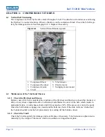
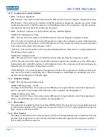
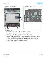
The basic panel components consist of a 16 I/O PLC Controller, Motor Starter with Overload Relay,
Control Power Transformer with fuses, Alarm and Warning Lights, Compressor Control Switch, Hour-
meter, Emergency Stop Switch, Starter Reset, Audible Alarm, terminal strip for wire connections and
wire harness.
To run the compressor, the Emergency Stop Switch must be pulled out and the Compressor Control
Switch must be in the ON position; at this point, the switch illuminates green and the compressor sys-
tem is ready and able to operate. If the pressure in the system drops to approximately 4500 psi
1
, the air
pressure switch will close, and the compressor will start. All other functions of the compressor are auto-
matic. When the air pressure has increased, and the pressure switch opens, then the compressor will
shutdown. All of these functions are accomplished through the use of a Programmable Logic Control-
ler. When use of the equipment is complete, the Compressor Control Switch should be placed in the Off
position.
7.2
Options
This panel will electrically support all commonly available compressor options offered by Bauer Com-
pressors. These include:
• The Securus
®
Electronic Moisture Monitoring System to monitor the air, and provide first a warning,
and later an alarm, to prompt the operator to replace the high pressure purification cartridges.
• The Carbon Monoxide Monitor is used to continuously sample the air that is compressed for use in
the system. Again, the unit will alarm and shut down the compressor if unsafe levels are detected. The
Carbon Monoxide Monitor also comes with a Calibration Kit to ensure accurate readings are being
taken.
• The Condensate High Level Alarm will alarm and shutdown the compressor when the condensate
level becomes too high. This Alarm is activated by a float switch in the ACD Condensate Collection
Tank. This alarm prompts the operator to drain the condensate and prevents spilled condensate.
7.3
AC Power Requirements
The panel will need to be supplied with the appropriate voltage(460), phase(3), and frequency(60Hz)
power to ensure proper operation. Wiring and conduit selection must be in accordance with all national,
state and local codes. The customer is responsible for providing a disconnection means and protection
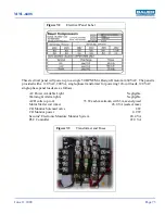
from instantaneous short circuit.The pre-wired panel voltage and phase is written on a label (See Figure
7-2) on the inside of the electrical panel door. In this example shown, the panel is wired for 460 volt,
three phase. If a schematic for your machine is not found inside the electrical panel, then please call
Bauer Compressors Product Support Group for a replacement. Please have the Serial number of the
compressor available.
1.
The pressure mentioned is only an example; the switch differential is approximately 10% of the set-point, and is not adjustable.

