MNL-0408
June 11, 2009
Page 77
7.4.8.1
PLC LED’s
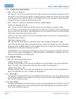
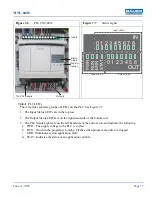
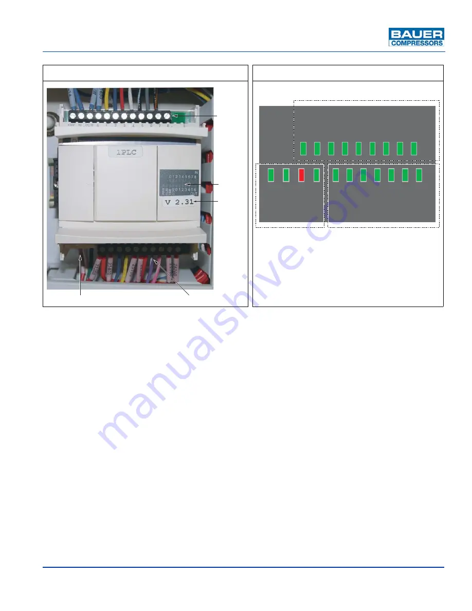
There are three separate groups of LED’s on the PLC. See Figure 7-7.
1. The Input Status LED’s are in the top row.
2. The Output Status LED’s are on the right hand side of the bottom row
3. The PLC Status Lights are on the left hand side of the bottom row and indicate the following.
a. PWR - The supply voltage to the PLC is correct.
b. RUN - On when the program is running. Flashes when program execution is stopped.
c. ERR - Illuminates red on application fault.
d. STAT - Indicates the status of an application variable.
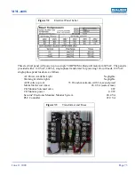
Figure 7-6
PLC CNT-0052
Figure 7-7
Status Lights
Inp
u
ts
O
u
tp
u
ts
Stat
u
s
Lights
Program
V
ersion
120
V
AC S
u
pply
IN
OUT
0 1 2 3 4 5 6
0 1 2 3 4 5 6 7 8
PWR RUN ERR S
TAT
Output LED’s
Status LED’s
Input LED’s

