MNL-0408
June 11, 2009
Page 83
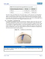
When the warning is illuminated, the unit will still continue to function properly, but will prompt the
operator to contact Bauer Compressors for making arrangements to replace the separator. When the
Alarm level has been achieved, the compressor will no longer function, and will require the replace-
ment of the separator. When this is accomplished, the unit can be re-activated by making adjustments to
the PLC. Please contact Bauer Product Support for detailed instructions.
7.6.7
Seven Flashes - Condensate Fault
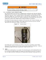
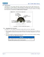
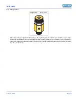
The compressor condensate level switch is located in the condensate collection tank, below the ACD,
Automatic Condensate Drain separator. The switch is N.O., Normally Open, and is connected to the
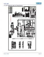
PLC on terminal I6. The switch is wired into a wire harness using the Grey and Pink color wires. Refer
to unit schematic for additional information. Under normal operating conditions, the switch is open
and the I6 lamp on the PLC is off. On a high condensate condition, the compressor will shutdown, the
I6 lamp will illuminate, and the alarm code will flash. The operator should drain the condensate from
the tank and resume operation of the equipment.
Table 7-5:
Final Separator Warning and Shutdown Cycle Count
Maximum Compressor Pressure
Warning
Shutdown
5,000 psi
117,000 cycles
130,000 cycles
6,000 psi
49,500 cycles
55,000 cycles
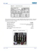
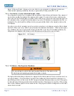
Figure 7-12
Condensate Level Float Switch
NOTICE
The compressor condensate contains some oil, and accordingly, should be disposed of in accordance with
state and local regulations.

