MNL-0408
June 11, 2009
Page 87
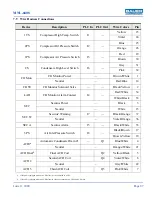
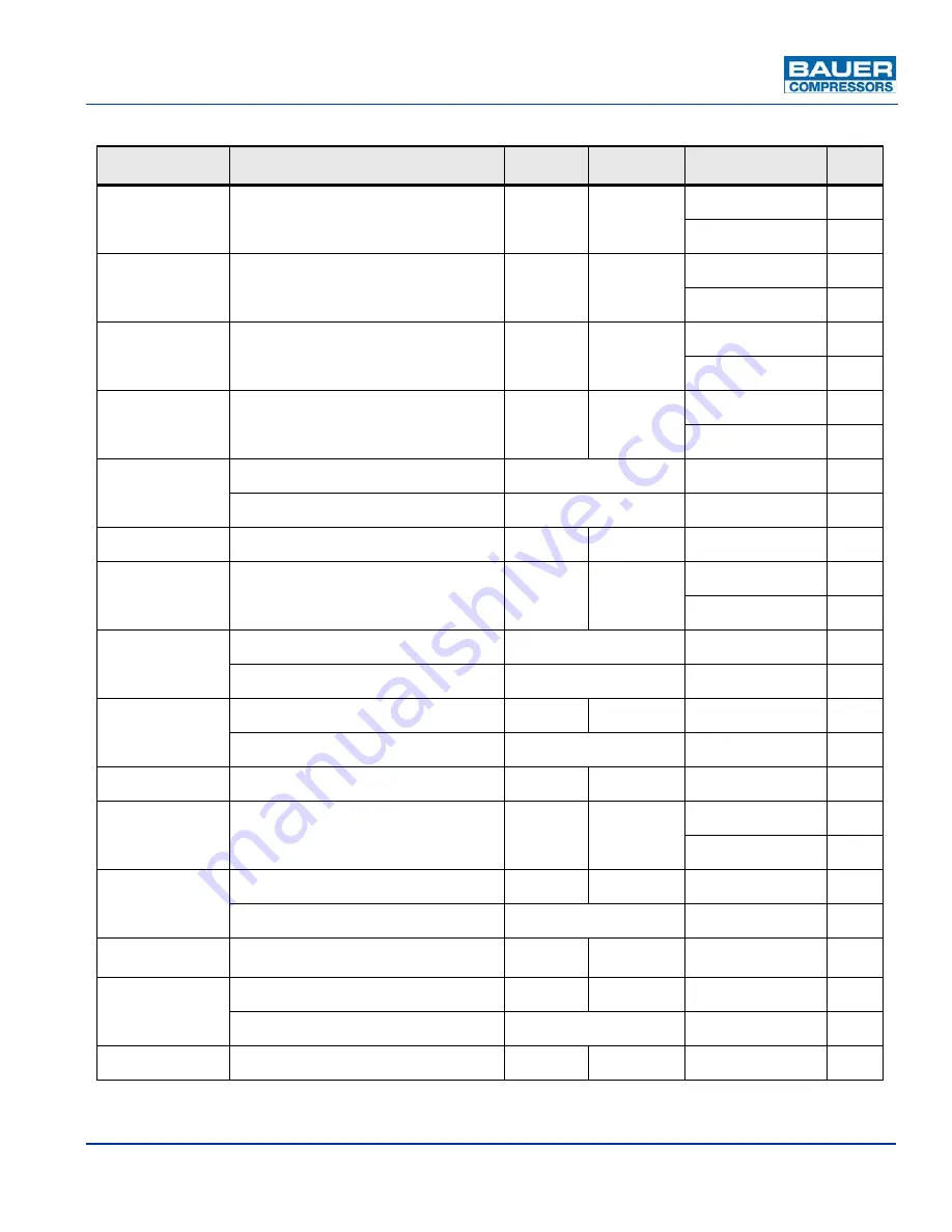
7.9
Wire Harness Connections
Device
Description
PLC In
PLC Out
Wire Colors
Pin
1TS
Compressor High Temp. Switch
I1
—
Yellow
23
Violet
24
2PS
Compressor Oil Pressure Switch
I2
—
Blue
25
Orange
26
1PS
Compressor Air Pressure Switch
I3
—
Red
29
Brown
30
CS
Condensate High Level Switch
I6
—
Grey
31
Pink
32
CO Mon.
CO Monitor Power
—
Brown/White
1
Neutral
—
Red/Blue
14
CO SV
CO Monitor Solenoid Valve
—
—
Black/Yellow
2
LAH
CO Monitor Alarm Contact
I4
—
Red/White
34
White/Black
33
SEC
Securus Power
—
Black
3
Neutral
—
White
15
SEC W
Securus
®
Warning
I7
—
Black/Orange
37
Neutral
—
Violet/Orange
36
SEC A
Securus Alarm
I5
—
Black/White
35
3 PS
Air Inlet Pressure Switch
I8
—
Black/Brown
17
Brown/Yellow
18
ACD1
a
a.
If the unit is equipped with one ACD Solenoid, it is connected to ACD1.
Automatic Condensate Drain #1
—
Q1
Blue/White
4
Neutral
—
Orange/White
21
ACD Final
b
b.
If the unit is equipped with two ACD Solenoids, they are connected to ACD1 and ACD Final.
Final ACD Coil
Q2
Yellow/Black
5
ACD 2
Second ACD Coil
Q4
Violet/White
6
Neutral —
Grey/White
22
ACD 3
Third ACD Coil
Q5
Pink/White
7

