MNL-0408
June 11, 2009
Page 25
5. Insert two 8mm diameter metal pins, any length, in the holes in the valve head and secure them in a
vise with the valve head on top of the vise. The intake valve (1) should be facing up.
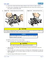
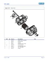
6. Using the special tool (See Figure 3-14) provided with the unit, remove the intake valve (1).
3.1.9.5.2
Reassembling the Valves of the 3rd Stage
1. Replace the intake valve (1) using the special tool to tighten it.
2. Check the intake valve functions correctly by blowing compressed air through the valve in the
direction of flow.
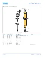
3. Secure the intake valve as follows: (See Figure 3-17) Peen the valve head aluminum over the screw-
in thread of the intake valve in two places opposite one another. Use a small drift pin, approximately
5mm in diameter.
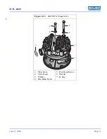
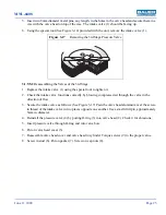
4. Reinstall the pressure valve (4) by putting O-ring (3) into valve head (2). Check it for abrasions.
5. Insert pressure valve through O-ring and into valve bore.
6. Put on valve head cover (5).
7. Reassemble valve head cover and valve head to cylinder. Torque screws (9) to the proper value.
8. Screw in stud (6). Put on gasket (7). Screw on cap nuts (8).
Figure 3-17
Removing the 3rd Stage Pressure Valve

