ImVT 120 II Mini Verticus
Page 56
1st Edition, Rev. 0 Chg. 10
5.1.3
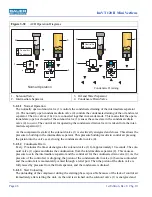
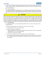
Manual Condensate Drainage
The condensate must be drained from the oil and water separator before changing any cartridge, before
beginning each filling procedure and in the absence of an Automatic Condensate Drain System, every fif-
teen minutes during the filling procedure. This is done by slowly opening the condensate drain valves.
They are opened approximately 1/3 of a turn to the left and held open until the condensate is completely
drained. The condensate drain valves close by spring pressure but if necessary may be tightened by hand
to ensure they are completely air tight.
5.1.4
Model, Serial Number and Part Number Identification
5.1.4.1
Compressor Dataplate
The model number, date of manufacture and serial number can be found on the compressor unit identifi-
cation plate in the main electrical enclosure and frame.
5.1.4.2
Purification System Dataplate
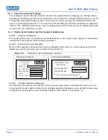
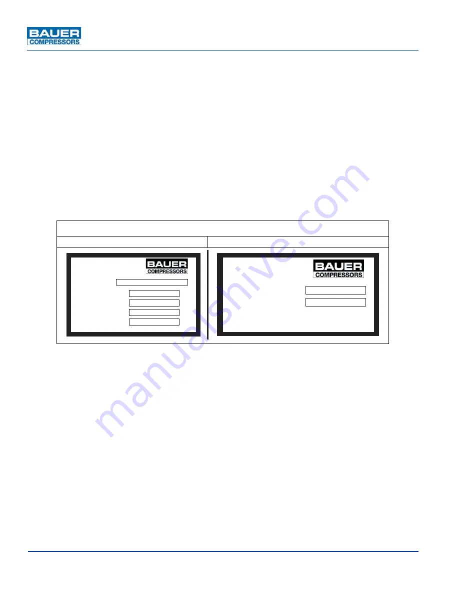
Refer to the compressor unit purification system dataplate (See Figure 5-2) on the compressor front to
determine your air processing system model and specifications.
5.1.4.3
Cartridge Installation Dataplate
The function performed by each chamber in the air processing system is determined by the type of car-
tridge installed in that chamber. Refer to the cartridge installation dataplate on the chamber to determine
the purpose and part number of the cartridge installed in that chamber. (See Figure 5-2).
Figure 5-2
Purification System Dataplates (typical)
Purification System
Cartridge Installation
CARTRIDGE FOR
CARTRIDGE NO.
LBL-
CARTRIDGE TO BE
INSTALLED
132
8
Azalea Garden Road - Norfolk Virginia 23502-1944
Phone: (757)
8
55-6006 Fax: (757)
8
55-
8
224
MODEL NO.
MAX. PRESSURE
AIR PROCESSED
O-RING
BACK-UP RING
psig
cu. ft.
LBL-
PURIFICATION
SYSTEM

