


2
ENGLISH
Original instructions
●
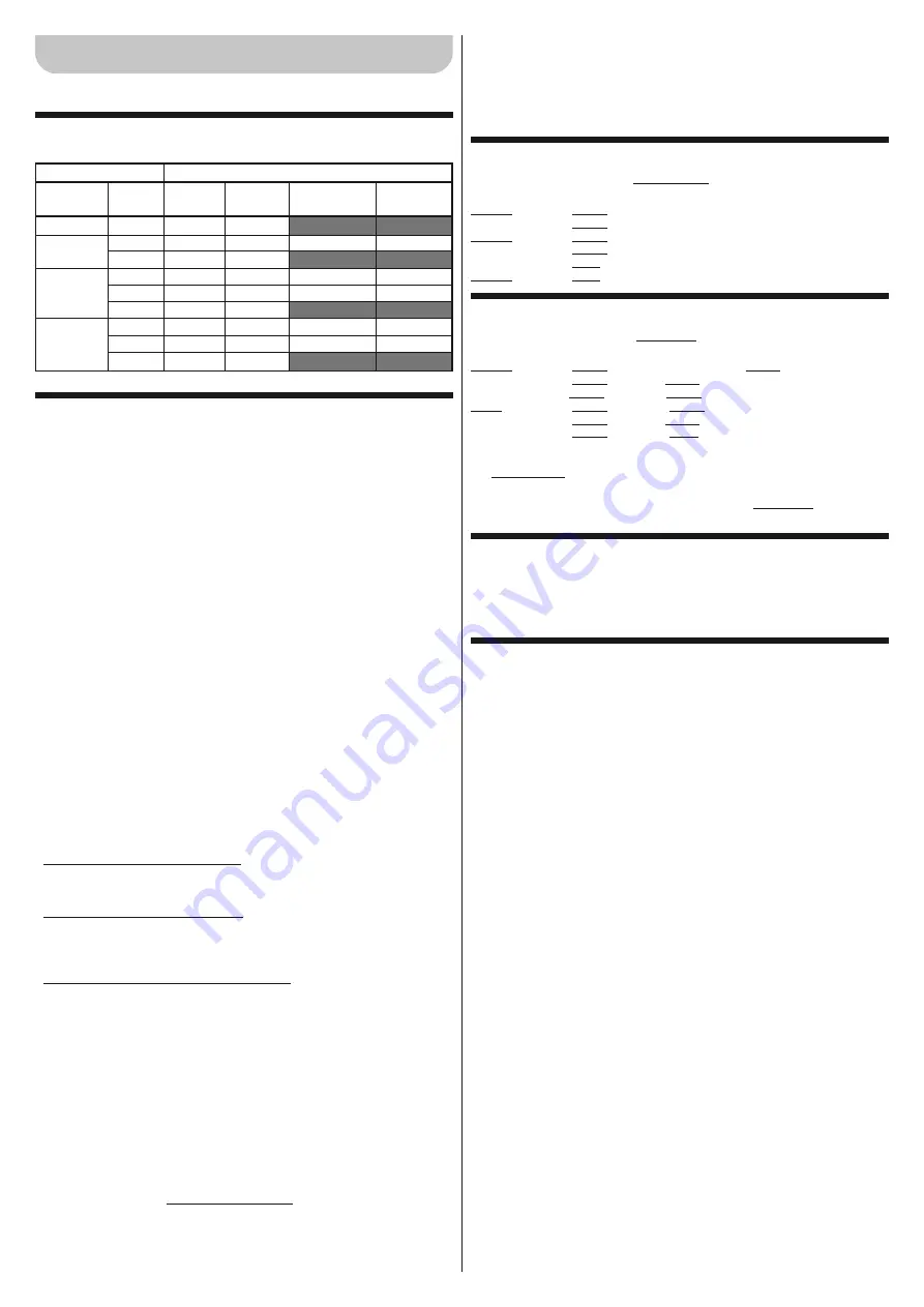
In chapter 2, replace the existing table with the table below.
●
In chapter 3, replace points 3.3, 3.3.1, 3.3.2, 3.3.3 with the
paragraphs appearing below.
3.3 - Preliminary work prior to installation
3.3.1 - Identify the scheme on the basis of which to position each plant com-
ponent
With reference to the standard layout shown in
fig. 1, locate the approximate po-
sition of each component in the system
. The diagram shows all components in
the product package (
fig. 3
): [
a
] road barrier with built-in control unit; [
b
] pole cover
and support; [
c
] no. 2 photocell boxes; [
d
] no. 4 half-shells for pole connection; [
e
]
fixed pole cap; no. 2 connections for protection rubber; no. 2 connections without pro-
tection rubber; [
f
] keys for manually locking and unlocking the pole; keys for locking
the cover; minor metal parts (screws, washers, etc.); [
g
] foundation plate; [
h
] no. 4 fix-
ing bolts.
3.3.2 - Determine the path of the connecting cables
CAUTION!
– Position the ends of the ducting used for electrical cables in the vicinity
of the points at which various components will be connected.
Note:
The ducting
serves to protect electric cables and prevent accidental damage, such as in the case
of impact. Prepare the electrical cables needed for your system, referring to
fig. 1
and “
Table 3
- Technical characteristics of electrical cables”.
3.3.3 - a) - Position the balancing spring in relation to pole weight, complete
with the required accessories. b) - Set the direction for closing the
pole: to the right or to the left of the motor.
The barrier leaves the factory with the following settings:
– balancing spring anchored in
holes which are not final
.
– pole closing manoeuvre
to the left
.
These settings are arbitrary; you must therefore perform the following checks to de-
termine whether they should be changed or not (that is, whether or not you need to
move the spring connection on the balancing lever and on the plate at the foot of the
barrier to another hole).
• If you plan to install only one accessory, identify in
box “A”
of
Table 4
your barrier
model, the planned pole length and, finally, the accessory you intend to assemble
on the pole; then read the corresponding letter and number of the holes in which to
hook the spring;
• If you plan to install multiple accessories, identify in
box “B”
of
Table 4
your barrier
model, pole length and, finally, the type and number of accessories you wish to as-
semble on the pole; then add up the numbers between brackets for the applicable
accessories. Finally, use the result of the sum to read the letter and number identi-
fying the holes to which to hook the spring in the lower part of box “B”.
• If you must close the pole to the right of the motor, it will be necessary to move the
spring connection to one of the holes on the other arm of the balancing lever.
Proceed as follows to hook the spring in a different hole from the factory settings:
01.
Remove the upper barrier cover (
fig. 4
).
02.
Loosen the 2 screws fixing the cabinet door (
fig. 5
).
03.
– (M3BAR - M5BAR - M7BAR) Turn the nut shown in
fig. 6
(step
a
) anti-clock-
wise and then manually turn the spring clockwise to slacken its tension (
fig. 6
-
step
b
).
– (LBAR) Turn the nut shown in
fig. 7
(step
a
) clockwise to slacken the tension
of the balancing spring.
04.
Slacken the bolt anchoring the spring to the balancing lever (M3BAR - M5BAR
- M7BAR:
fig. 6
- step
c
; LBAR:
fig. 7
- step
b
).
05.
– (M3BAR - M5BAR) Slacken the bolt anchoring the spring to the perforated
plate positioned at the foot of the barrier (
fig. 6
- step
d
).
– (M3BAR - M5BAR) Slacken the bolt anchoring the spring to the perforated
plate positioned at the foot of the barrier (
fig. 7
- step
c
).
06.
If you wish to set the pole to close on the right of the barrier, slacken the gear-
motor (
fig. 8
- also refer to point 3.6) and turn the balancing lever 90° (
fig. 9
).
07.
Use
Table 4
to identify the new holes to which to hook up the two ends of the
spring.
08.
– (M3BAR - M5BAR) Hook the spring plate to the peforated plate at the foot of
the barrier (
fig. 10
- step
a
) then anchor the eye of the spring to the balancing
lever, tightening the bolt all the way (
fig. 10
- step
b
)
– (M7BAR - LBAR) Anchor the upper eye of the spring to the balancing lever,
tightening the bolt all the way (
fig. 11
- step
a
); anchor the lower eye of the spring
to the perforated plate at the foot of the barrier, tightening the bolt all the way (
fig.
11
- step
b
).
09.
If you slackened the gearmotor at point 06, tighten it again (
fig. 12
), referring to
point 3.6.
●
Additional information on point 3.5.2
Assembling a pole formed of a single piece, whole or cut.
Possible lengths:
M3BAR
:
2.65
m = XBA15 (3.15 m -0.50 m = 2.65 m)
3.15
m = XBA15 (3.15 m)
M5BAR
:
3.50
m = XBA14 (4.15 m -0.65 m = 3.50 m)
4.15
m = XBA14 (4.15 m)
5.15
m = XBA5 (5.15 m)
M7BAR
:
5.15
m = XBA5 (5.15 m)
●
Additional information on point 3.5.3
Assembling a pole formed of two pieces, either whole or cut.
Possible lengths:
M7BAR
:
5.00
m = XBA15 (3.15 m -1.30m = 1.85
*
) + XBA15 (3.15 m)
6.33
m = XBA15 (3.15 m) + XBA15 (3.15 m)
7.33
m = XBA15 (3.15 m
*
) + XBA14 (4.15 m)
LBAR
:
7.33
m = XBA15 (3.15 m
*
) + XBA14 (4.15 m)
8.33
m = XBA14 (4.15 m) + XBA14 (4.15 m)
9.33
m = XBA14 (4.15 m
*
) + XBA5 (5.15 m)
________
(*) - CAUTION! – In rods made up of two pieces, it is obligatory to anchor
the shorter piece to the aluminium support. Point 02 of the procedure must
therefore be changed as follows:
02.
Insert the assembled connection on one end of the shorter pole using a rubber
mallet.
●
Addition of a new point: 3.5.4
3.5.4 - Installation of required pole accessories
After installing the pole and the protection rubber, before proceeding any further it is
important to install any other accessories that may be required on the pole. For in-
structions on installation of these accessories, refer to their instruction manuals.
●
In chapter 3, replace points 3.6, 3.6.1, 3.7, 3.8, 3.8.1, 3.8.2
with the following.
3.6 - Manually releasing and locking the barrier
This operation is required in the event of a power failure or malfunction.
To manually release or lock the barrier, insert the key provided and turn it 180° to the
right or to the left (
fig. 32
).
IMPORTANT!
•
The release and locking operations must be performed only
when the pole is horizontal and stationary. • It is possible to carry out the
manual release and lock on both sides of the barrier by moving the locking
cylinder (see paragraph 3.6.1).
3.6.1 - How to move the locking cylinder for manual release and lock
01.
Insert the key supplied and turn through 180° clockwise (
fig. 33-a
);
02.
From inside the caisson, pull the U-shaped clip holding the lock cylinder in place
(
fig. 33-b
) and pull off the cylinder on the outside of the caisson(
fig. 33-c
);
03.
From the other side of the caisson, remove the plastic cap (
fig. 34-a
) and insert
the lock cylinder into the hole provided (
fig. 34-b
);
04.
Finally, from inside the caisson, insert the U-shaped clip for holding the locking
cylinder in place from below (
fig. 34-c
).
3.7 - Limit switch mechanical stop adjustment
01.
Manually release the gearmotor: see paragraph 3.6;
02.
Manually move the pole through a complete Opening and Closing manoeuvre;
03.
Then use the screws on the mechanical limit switch stops (
fig. 35
and
36
) to ad-
just the horizontal pole setting, when it is closed, and the vertical pole setting,
when it is open.
04.
Tighten the nuts well.
3.8 - Pole balancing
Balancing the pole serves to find the best balance between the total pole
weight
complete with the accessories installed and the
force
opposed to it by the tension
of the balancing spring. Proceed as follows to check whether spring tension is ap-
propriate to balance the weight of the pole and its accessories, if any.
3.8.1 - M3BAR / M5BAR / M7BAR Pole balancing
01.
Manually release the gearmotor: see paragraph 3.6;
02.
Manually move the pole to mid-travel (45°) and leave stationary. If the pole tends
to lift, reduce the tension of the spring by manually turning it clockwise (
fig. 37-
a
). If, on the contrary, the pole tends to drop, increase spring tension by manu-
ally turning it clockwise (
fig. 37-b
).
Note - the off-balance value is only accept-
able when the force required to move the pole
*
when open, closed and in all the
other positions, is lower than or equal to half of the nominal value (equal to
about 1.5 kg for M3; 3.5 kg for M5 and 4.5 kg for M7, about 5 kg at 1 m).
[(
*
)
Cabinet
M3BAR
M5BAR
M7BAR
LBAR
Pole
3 m
4 m
5 m
5 m
3+3 m
3+4 m
3+4 m
4+4 m
4+5 m
Rubber
✔
✔
✔
✔
✔
✔
✔
✔
✔
Lights
✔
✔
✔
✔
✔
✔
✔
✔
✔
Rack
✔
(1 piece)
✔
(2 pieces)
✔
(2 pieces)
✔
(3 pieces)
✔
(3 pieces)
Mobile
support
✔
✔
✔
✔
✔
Installable accessories
Summary of Contents for LBar
Page 15: ...III 7 c a b LBAR 90 9 8 ...
Page 16: ...IV 10 a b M3BAR M5BAR 11 b a LBAR ...
Page 17: ...V 12 17 19 32 ...
Page 18: ...VI 33 34 c a b c a b 45 45 37 45 45 38 a b a b c ...
Page 19: ...VII STOP 45 52 ...
Page 20: ...IS0204A00MM_23 07 2012 ...


