


3
force measured at right angles to the pole and at 1 m from the rotation axis].
03.
Repeat point 02 positioning the pole also at approx. 20° and approx. 70°. If the
pole remains still in position, this means that balancing is correct; a slight off bal-
ance is admissible,
but the pole must never move significantly
.
04.
Lock the balancing spring in place with the nut (
fig. 37-c
);
05.
Manually lock the gearmotor: see paragraph 3.6.
3.8.2 - LBAR Pole balancing
01.
Manually release the gearmotor: see paragraph 3.6;
02.
Manually move the pole to mid-travel (45°) and leave stationary. If the pole tends
to lift, reduce the tension of the spring by manually turning the nut clockwise
(
fig. 38-a
). If, on the contrary, the pole tends to drop, increase spring tension by
turning the nut anti-clockwise (
fig. 38-b
).
Note - the off-balance value is only
acceptable when the force required to move the pole
*
when open, closed and
in all the other positions, is lower than or equal to half of the value of the nomi-
nal torque (for this product, about 6.5 kg at 1 m).
[(
*
) force measured at right
angles to the pole and at 1 m from the rotation axis].
03.
Manually lock the gearmotor: see paragraph 3.6.
●
In chapter 4, replace points 4.5 and 4.10 with the following:
4.5 - Recognition of limit positions on opening and closing
After learning the connected devices, the control unit also has to learn the positions
of the mechanical stops. In this phase, the pole travel distance is read, measured
from the closing mechanical stop to the opening mechanical stop.
01.
Manually release the gearmotor (see chapter 3.6) and manually position the
pole at approx. 45° (mid-travel);
02.
Lock the gear motor (see paragraph 3.6);
03.
Press and hold down “
Close
” and “
Set
” keys at the same time;
04.
Release the keys when the manoeuvre starts (after approx. 3 seconds);
05.
Wait a few seconds for the control unit to complete the position learning phase:
close, open and close of the pole, with intervals with a 3 second pause.
Warnings!
• Do not interrupt the three manoeuvres: if they are interrupted, it
will be necessary to repeat the entire procedure from point 01. • While perform-
ing the three manoeuvres, make sure that the pole balancing lever hits the
mechanical stops on the limit switches. If this does not happen, stop the proce-
dure, adjust the mechanical stops on the limit switch and repeat the procedure
from point 01. • If leds “L3” and “L4” flash after completion of the three
manoeuvres, an error has occurred. In this case, repeat the entire procedure
starting from step 01.
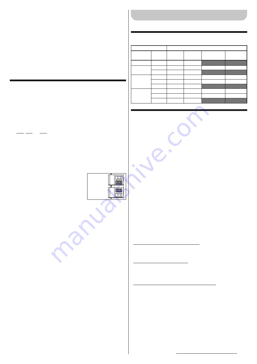
4.10 - Connection of other devices
The built-in unit enables the power supply to the
external devices (a radio receiver or the key-operated
selector switch lighting) by receiving power from the
control unit: for the type of electrical connection, refer
to the figure at the side. The power supply voltage is
24 Vdc, -30%/+50%, with maximum available current
100 mA.
P. P.
STOP
24Vcc (+)
GND (+)
●
Nel capitolo 2 sostituire la tabella essitente con la seguente
tabella.
●
Nel capitolo 3 sostituire i paragrafi 3.3, 3.3.1, 3.3.2, 3.3.3 con
i seguenti paragrafi.
3.3 - Lavori preliminari all’installazione
3.3.1 - Stabilire lo schema col quale posizionare ogni componente dell’im-
pianto
Stabilire la posizione approssimativa in cui verrà installato ciascun componente pre-
visto nell’impianto, facendo riferimento allo schema standard mostrato in
fig. 1
. Nel-
lo schema sono riportati tutti i componenti presenti nell’imballo del prodotto (
fig. 3
):
[
a
] barriera stradale con centrale di comando incorporata; [
b
] supporto e coperchio
asta; [
c
] n°2 box per fotocellule; [
d
] n°4 semigusci per innesto asta; [
e
] tappo asta
fisso; n°2 innesti per gomma paracolpi; n°2 innesti senza gomma paracolpi; [
f
] chia-
vi per lo sblocco e il blocco manuale dell’asta; chiavi per serratura del coperchio;
minuteria metallica (viti, rondelle, ecc.); [
g
] piastra di fondazione; [
h
] n° 4 zanche di
fissaggio.
3.3.2 - Stabilire il percorso dei cavi di collegamento
ATTENZIONE!
– Posizionare le estremità dei tubi per il passaggio dei cavi elettrici, in
prossimità dei punti in cui è stato previsto il fissaggio dei vari dispositivi.
Nota:
I tubi
hanno lo scopo di proteggere i cavi elettrici ed evitare rotture accidentali, ad esempio
in caso di urti. Per preparare i cavi elettrici necessari al vostro impianto, fare riferi-
mento alla
fig. 1
e alla “
Tabella 3
- Caratteristiche tecniche dei cavi elettrici”.
3.3.3 - a) - Posizionare la molla di bilanciamento in relazione al peso del-
l’asta, completa degli accessori previsti. b) - Impostare la direzione di
chiusura dell’asta: a destra o a sinistra del motore.
L’alzabarriera esce dalla fabbrica impostata nel modo seguente:
– molla di bilanciamento ancorata in
fori che non sono definitivi
.
– manovra di
chiusura dell’asta orientata a sinistra
.
Queste impostazioni sono arbitrarie; quindi è necessario effettuare le seguenti verifi-
che per capire se devono essere cambiate oppure no (cioè, se occorre o meno spo-
stare in altri fori l’aggancio della molla sulla leva di bilanciamento e sulla piastra ai pie-
di dell’alzabarriera).
• Se si prevede di installare un singolo accessorio, individuare nel
riquadro “A”
del-
la
Tabella 4
il vostro modello di alzabarriera, la lunghezza dell’asta prevista e, infi-
ne, l’accessorio che si intende montare sull’asta; quindi, leggere in corrispondenza
di questi dati la lettera e il numero relativi ai fori da scegliere per l’aggancio della
molla;
• Se si prevede di installare più accessori, individuare nel
riquadro “B”
della
Tabel-
la 4
il vostro modello di alzabarriera, la lunghezza dell’asta prevista e, infine, il tipo
e il numero di accessori che si desidera montare sull’asta; quindi, sommare i
numeri tra parentesi legati agli accessori previsti. Infine, utilizzare il risultato della
somma per leggere, nella parte bassa del riquadro “B”, la lettera e il numero relati-
vi ai fori da scegliere per l’aggancio della molla.
• Se la chiusura dell’asta deve avvenire alla destra del motore, sarà necessario spo-
stare l’aggancio della molla in uno dei fori presenti sull’altro braccio della leva di
bilanciamento.
Per spostare l’aggancio della molla in fori diversi dall’impostazione di fabbrica, pro-
cedere nel modo seguente:
01.
Togliere il coperchio superiore dell’alzabarriere (
fig. 4
).
02.
Svitare le 2 viti che fissano la porta armadio (
fig. 5
).
03.
– (M3BAR - M5BAR - M7BAR) Girare in senso antiorario il dado mostrato in
fig.
6
(fase
a
); quindi ruotare manualmente la molla in senso orario per allentare la
sua tensione (
fig. 6
- fase
b
).
– (LBAR) Girare in senso orario il dado mostrato in
fig. 7
(fase
a
) per allentare la
tensione della molla di bilanciamento.
04.
Svitare il bullone che àncora la molla alla leva di bilanciamento (M3BAR -
M5BAR - M7BAR:
fig. 6
- fase
c
; LBAR:
fig. 7
- fase
b
).
05.
– (M3BAR - M5BAR) Sganciare la zanca che àncora la molla alla piastra forata,
posizionata ai piedi dell’alzabarriera (
fig. 6
- fase
d
).
– (M7BAR - LBAR) Svitare il bullone che àncora la molla alla piastra forata, posi-
zionata ai piedi dell’alzabarriera (
fig. 7
- fase
c
).
06.
Se si desidera impostare la manovra di chiusura dell’asta sul lato destro dell’al-
ITALIANO
Istruzioni originali
Armadio
M3BAR
M5BAR
M7BAR
LBAR
Asta
3 m
4 m
5 m
5 m
3+3 m
3+4 m
3+4 m
4+4 m
4+5 m
Gomma
✔
✔
✔
✔
✔
✔
✔
✔
✔
Luci
✔
✔
✔
✔
✔
✔
✔
✔
✔
Rastrelliera
✔
(1 pezzo)
✔
(2 pezzi)
✔
(2 pezzi)
✔
(3 pezzi)
✔
(3 pezzi)
Appoggio
Mobile
✔
✔
✔
✔
✔
Accessori installabili
Summary of Contents for LBar
Page 15: ...III 7 c a b LBAR 90 9 8 ...
Page 16: ...IV 10 a b M3BAR M5BAR 11 b a LBAR ...
Page 17: ...V 12 17 19 32 ...
Page 18: ...VI 33 34 c a b c a b 45 45 37 45 45 38 a b a b c ...
Page 19: ...VII STOP 45 52 ...
Page 20: ...IS0204A00MM_23 07 2012 ...


