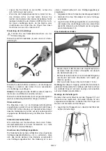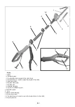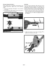
Remove transport protection
Before starting with the installation as described in the
operating instructions, please carry out the following
steps:
1. Pull the inner telescopic tube approx. 5 cm out of the
outer sleeve.
2. Then remove the rubber stopper. This is only required
as transport protection for the cable.
ca. 5 cm
1
2
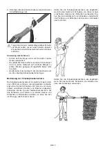
Assembly
There are three lugs inside the tube sleeve (A) on the
cutter head which must engage in the recesses in the
hexagonal tube. Place the device on a level surface as
shown in the figure below. The side of the hexagonal tube
in which there is only one recess must face upwards (B).
1. Slide the cutter head onto the tube in this position (to
do so, screw sleeve 14 must be loosened by turning
anticlockwise ( )). The lugs must engage audibly in
the recesses.
14
A
B
2. Tighten screw sleeve 14 by turning it clockwise ( ) to
fasten the cutter head on the tube.
14
GB-10
Summary of Contents for GHTI 60 Gardol
Page 170: ......
Page 171: ...BG 1 2 3 4 5 6 9 10 11 13 15 15 15 15 15 16...
Page 172: ...20 mm BG 2...
Page 173: ...1 2 3 4 1 5 6 7 8 9 ON OFF 10 11 12 13 14 2 15 BG 3 11 14 15 1 2 3 4 5 6 7 8 12 9 10 13...
Page 175: ...BG 5 II 10m 104 dB A...
Page 176: ...BG 6 1 a b c 2 a b c d e f residual current device RCD RCD 3 a b c...
Page 177: ...BG 7 ON d e f g 4 a b c d e f g 5 a...
Page 178: ...BG 8 16...
Page 179: ...30 mA 1 2 3 15 50 4 5 6 7 8 9 BG 9...
Page 180: ...50 15m 10 50 15m 1 2 3 4 5 6 7 8 1 2 1 5 cm 2 BG 10...
Page 181: ...ca 5 cm 1 2 A 1 14 14 A B 2 14 BG 11 14 120 1 3 2 5 30 0 30 60 90...
Page 182: ...BG 12 30 30 60 90 0 3 3 3 4 4 5 5 4 II VDE 0740 30mA 1 OFF 2 3 13...
Page 183: ...BG 13 9 10 13 9 10 9 10 1 2 6 7 6...
Page 184: ...BG 14...
Page 185: ...BG 15 20 mm 1 2 3 2012 19 EC...
Page 186: ...BG 16 60...
Page 286: ......
Page 288: ......
Page 289: ......

