


www.Bauhaus.info
13.01.17
4
Please note the structural data and concrete quality required for the foundations.
Post anchors and bolts are not provided in the delivered contents.
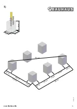
1) Foundation
The surface of the building site should be level. Begin by excavating the holes
for the post footings according to the dimensions given in the foundation plan below.
It is extremely important that the foundations are positioned at right angles.
Tip!
Use a wooden stake to mark the location of a post. Then mark out a right
angle from that corner. If the diagonal measured between sides that are exactly
4m and 3m long equals exactly 5m, you have created a right angle.
As an alternative method, it is possible to verify that you have a right angle
using the dimensions given below.
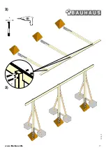
2) Posts and girders
It is now possible to attach the posts to the girders. First lay the girders on the
ground and arrange the posts as specified in the plan. Use a screw clamp to
attach the posts to the girder and then drill through both components using a
7mm wood drill bit. Use the machine screws to connect the girder and posts.
Now pre-drill for the post anchors and attach them to the posts. Use roof
battens to reinforce the construction (drawing 1).
Erect the completed side sections and position them in the footings. Brace the
side sections and align the entire unit (drawing 1)
Warning: Position the posts with the splice joint facing inwards
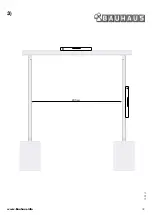
3)
After both side sections have been erected, position the entire construction as
shown in drawing 3. Align the carport from the front to the back with a 1%
slope (see plan drawing on the last page).
Now it is possible to pour the concrete footings.
Smooth the surface of the footings to gently slope outwards. This allows for
better drainage of rainwater.
After verifying the dimensions, it is possible to pour the concrete foundations.
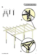
4) Girders, rafters and diagonal supports
Place the rafters on the girders as shown in the drawing and connect them
using the Rafter anchors. If the rafters are slightly bowed, place the rafter so
that it arches upwards and position it as far forward as possible.
5)
Install the diagonal supports transversely on every post (see plan drawing
on the last page).
6) Roof panels
After all of the rafters have been attached, install the roof panels. Make sure
to install the panels from the back to the front. First distribute the roof panels
on the rafters so that they fit across the breadth and then over the length
of the carport. It is essential to distribute and align all of the panels before
screwing down the panels! The distance from the edge fascia should amount
to at least 5mm.
Attach every roof panel using at least 4 spacers and screws per rafter. Our
hardware system makes it possible complete the assembly without help from
a third party.
Warning:
only walk on the panels using planks to distribute the weight.
It is necessary to observe the information provided on the first page.
7)
Step 1:
Drill through the roof panel at a slow speed using a 10mm wood drill bit.
Make sure that the drill is horizontal and centred. Drilling at an unsuitable
speed can break the panel.
Step 2:
Place the plastic spacer in the hole. Place the screw bit directly in the spacer
to drive it through the panel.
Step 3:
Verify the correct positioning of the spacer. The roof panel must be resting
on the spacer.
Step 4:
Now securely screw the roof panel to the rafter. Make sure to drive the screw
straight through the panel. Otherwise leakage may occur.
Step 5:
Do not over-tighten the screw, as this may damage the roof panel.
8) Fascia boards
Begin with the front fascia board. Install the front fascia board to project by
2cm beyond the rafters on both the left and right sides.
Attach the fascia boards on the sides using Phillips-head screws in the
ends of the rafters (please pre-drill).
The fascia boards should project beyond the roof panels by 0.5cm.
Special Offer Carport (GB)
Assembly Instructions
Page 16
Page 17
Page 17/18
Page 19
Page 20
Page 20
Page 21
Summary of Contents for Special Offer Carport
Page 15: ...www Bauhaus info 13 01 17 15 10 30 20 40 51 50 10 10 10 10 20 40 51 40 40 40 40 30...
Page 17: ...www Bauhaus info 13 01 17 17 e M10 x 100 2 3 e...
Page 18: ...www Bauhaus info 13 01 17 18 245 cm 3...
Page 19: ...www Bauhaus info 13 01 17 19 c 4 5 c c 5 c 4 x 45 b 3 5 x 25 a 35 x 35 x 170 b b...
Page 20: ...www Bauhaus info 13 01 17 20 1 2 3 4 5 6 7...
Page 21: ...www Bauhaus info 13 01 17 21 i 3 5 x 35 8 i i i...


