12
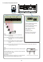
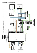
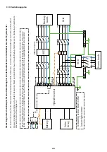
3.4 Eingangs-/Ausgangsverbindung
- Vor dem Anschluss an das Stromnetz installieren Sie bitte einen separaten AC-Schutzschalter zwischen Wech-
selrichter und Netz. Dadurch wird sichergestellt, dass der Wechselrichter während der Wartung sicher getrennt
werden kann und vollständig vor Überstrom geschützt ist. 20A für 8kW, 32A für 10kW und 32A für 12KW sind die
empfohlenen Werte für den AC-Schutzschalter für den Lastanschluss. Der empfohlene AC-Unterbrecher für den
Netzanschluss ist 63A für 8kW, 63A für 10kW und 63A für 12KW.
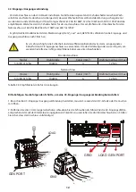
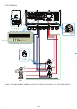
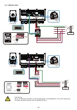
- Es gibt drei Klemmenblöcke mit den Markierungen „Netz“, „Last“ und „GEN“. Bitte schließen Sie die Eingangs- und
Ausgangsanschlüsse nicht falsch an.
Tabelle 3-3 Empfohlene Größe für AC-Leitungen
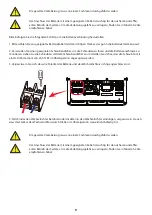
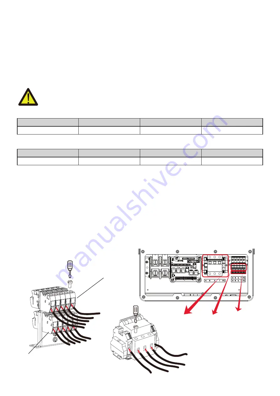
Bitte befolgen Sie die folgenden Schritte, um eine AC-Eingangs-/Ausgangsverbindung herzustellen:
1. Bevor Sie die AC-Eingangs-/Ausgangsverbindung herstellen, müssen Sie zuerst den DC-Schutz oder Trennschal-
ter öffnen.
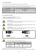
2. Entfernen Sie die 10 mm lange Isolierhülse, schrauben Sie die Schrauben ab, führen Sie die AC-Eingangsdrähte
entsprechend der auf der Klemmleiste angegebenen Polarität ein und ziehen Sie die Klemmschrauben an. Stellen
Sie sicher, dass der Anschluss vollständig ist.
Es ist sehr wichtig für die Sicherheit und den effizienten Betrieb des Systems, ein geeignetes
Kabel für den AC-Eingangsanschluss zu verwenden. Um das Verletzungsrisiko zu verringern, ver-
wenden Sie bitte das richtige empfohlene Kabel wie unten beschrieben.
- 08 -
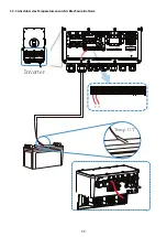
Please follow below steps to implement ba�ery connec�on:
1. Please choose a suitable ba�ery cable with correct connector which can well fit into the
ba�ery terminals. 2. Use a suitable screwdriver to unscrew the bolts and fit the ba�ery
connectors in, then fasten the bolt by the screwdriver, make sure the bolts are �ghtened
with torque of 24.5 N.M.
2. Nm in clockwise direc�on, make sure polarity at both the ba�ery and inverter is correctly
connected.
Connec�ng the ba�ery with a suitable cable is important for safe and efficient
opera�on of the system. To reduce the risk of injury, refer to Chart 3-2 for
recommended cables.
All wiring must be performed by a professional person.
3. In case of children touch or insects go into the inverter, Please make sure the inverter
connector is fasten to waterproof posi�on by twist it clockwise.
Before making the final DC connec�on or closing DC breaker/disconnect, be sure
posi�ve(+) must be connect to posi�ve(+) and nega�ve(-) must be connected to
nega�ve(-). Reverse polarity connec�on on ba�ery will damage the inverter.
Installa�on must be performed with care.
For 3.6KW/5KW model, ba�ery connector screw size: M6
Model
Drahtgröße
Kabel (mm2)
Drehmomentwert (max)
5/6/8/10/12Kw
10AWG
4
1.2Nm
Model
Drahtgröße
Kabel (mm2)
Drehmomentwert (max)
5/6/8/10/12Kw
10AWG
6
1.2Nm
Ersatzlastanschluss
Netzanschluss
- 12 -
GRID
LOAD GEN PORT
3.4 Grid connec�on and backup load connec�on
1. Before making Grid, load and Gen port connec�on, be sure to turn off AC baeaker or
disconnector first.
2. Remove insula�on sleeve 10mm length, unscrew the bolts, insert the wires according to
polari�es indicated on the terminal block and �ghten the terminal screws. Make sure the
connec�on is complete.
Please follow below steps to implement Grid, load and Gen port connec�on:
Chart 3-3 Recommended Size for AC wires
· Before connec�ng to grid, please install a separate AC breaker between inverter and grid. Also,
it is recommended that installs an AC breaker between backup load and inverter.This will ensure
the inverter can be securely disconnected during maintenance and fully protected from over
current.The recommended of AC breaker for the load port is 20A for 8kw, 32A for 10kw and
32A for 12KW
.
The recommended of AC breaker for the grid port is 63A for 8kw, 63A for 10kw
and 63A for 12KW.
All wiring must be performed by a qualified personnel.It is very important for
system safety and efficient opera�on to use appropriate cable for AC input
connec�on. To reduce risk of injury, please use the proper recommended cable
as below.
GRID
T
(L3)
PE
S
(L2)
R
(L1)
N
T
(L3)
PE
S
(L2)
R
(L1)
N
T
(L3)
PE
S
(L2)
R
(L1)
GEN PORT
LOAD
Grid connec�on
backup load connec�on
· There are three terminal blocks with "Grid" "Load"and "GEN" markings. Please do not misconnect
input and output connectors.
Model
5/6/8/10/12KW
Wire Size
10AWG
Cable(mm )
2
4
Torque value(max)
1.2Nm
Model
5/6/8/10/12KW
Wire Size
10AWG
Cable(mm )
2
6
Torque value(max)
1.2Nm
N
N
R S
T
PE

