14
3.5 Auswahl der PV-Module:
Bei der Auswahl der richtigen PV-Module sollten Sie die folgenden Parameter beachten:
1) Die Leerlaufspannung (Voc) der PV-Module darf die max. PV-Generator-Leerlaufspannung des Wechselrichters.
2) Die Leerlaufspannung (Voc) der PV-Module sollte höher sein als die minimale Startspannung.
3.5.2 PV-Modul-Drahtverbindung:
1. Schalten Sie den Hauptschalter der Netzversorgung (AC) aus.
2. Schalten Sie den Gleichstromsolator AUS.
3. Schließen Sie den PV-Eingangsstecker an den Wechselrichter an.
Inverter Model
5KW
6KW
8KW
10KW
12KW
PV-Eingangsspannung
550V (160V~800V)
PV-Array MPPT Spannungsbereich
200V-650V
Anzahl der MPP-Tracker
2
Anzahl der Strings pro MPP-Tracker
1+1
1+1
1+1
2+1
2+1
Sicherheitshinweis:
Bitte schließen Sie weder den Plus- noch den Minuspol des PV-Generators an die Erde an, da dies
zu schweren Schäden am Wechselrichter führen kann.
Sicherheitshinweis:
Vergewissern Sie sich vor dem Anschluss, dass die Polarität der Ausgangsspannung des PV array
mit den Symbolen „DC+“ und „DC-“ übereinstimmt.
Sicherheitshinweis:
Vergewissern Sie sich vor dem Anschluss des Wechselrichters, dass die Leerlaufspannung des PV-
Generators innerhalb der 1000 V des Wechselrichters liegt.
- 08 -
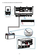
Please follow below steps to implement ba�ery connec�on:
1. Please choose a suitable ba�ery cable with correct connector which can well fit into the
ba�ery terminals. 2. Use a suitable screwdriver to unscrew the bolts and fit the ba�ery
connectors in, then fasten the bolt by the screwdriver, make sure the bolts are �ghtened
with torque of 24.5 N.M.
2. Nm in clockwise direc�on, make sure polarity at both the ba�ery and inverter is correctly
connected.
Connec�ng the ba�ery with a suitable cable is important for safe and efficient
opera�on of the system. To reduce the risk of injury, refer to Chart 3-2 for
recommended cables.
All wiring must be performed by a professional person.
3. In case of children touch or insects go into the inverter, Please make sure the inverter
connector is fasten to waterproof posi�on by twist it clockwise.
Before making the final DC connec�on or closing DC breaker/disconnect, be sure
posi�ve(+) must be connect to posi�ve(+) and nega�ve(-) must be connected to
nega�ve(-). Reverse polarity connec�on on ba�ery will damage the inverter.
Installa�on must be performed with care.
For 3.6KW/5KW model, ba�ery connector screw size: M6
Bitte verwenden Sie für die PV-Anlage zugelassene DC-Kabel.
- 08 -
Please follow below steps to implement ba�ery connec�on:
1. Please choose a suitable ba�ery cable with correct connector which can well fit into the
ba�ery terminals. 2. Use a suitable screwdriver to unscrew the bolts and fit the ba�ery
connectors in, then fasten the bolt by the screwdriver, make sure the bolts are �ghtened
with torque of 24.5 N.M.
2. Nm in clockwise direc�on, make sure polarity at both the ba�ery and inverter is correctly
connected.
Connec�ng the ba�ery with a suitable cable is important for safe and efficient
opera�on of the system. To reduce the risk of injury, refer to Chart 3-2 for
recommended cables.
All wiring must be performed by a professional person.
3. In case of children touch or insects go into the inverter, Please make sure the inverter
connector is fasten to waterproof posi�on by twist it clockwise.
Before making the final DC connec�on or closing DC breaker/disconnect, be sure
posi�ve(+) must be connect to posi�ve(+) and nega�ve(-) must be connected to
nega�ve(-). Reverse polarity connec�on on ba�ery will damage the inverter.
Installa�on must be performed with care.
For 3.6KW/5KW model, ba�ery connector screw size: M6
3.5.1 PV Module Selec�on:
3.5.2 PV Module Wire Connec�on:
When selec�ng proper PV modules, please be sure to consider below parameters:
1) Open circuit Voltage (Voc) of PV modules not exceeds max. PV array open circuit voltage of
inverter.
2) Open circuit Voltage (Voc) of PV modules should be higher than min. start voltage.
Chart 3-5
- 14 -
1. Switch the Grid Supply Main Switch(AC)OFF.
2. Switch the DC lsolator OFF.
3. Assemble PV input connector to the inverter.
Safety Hint:
Please don’t connect PV array posi�ve or nega�ve pole to the ground, it could
cause serious damages to the inverter.
Safety Hint:
Before connec�ng inverter, please make sure the PV array open circuit voltage is
within the 1000V of the inverter.
Safety Hint:
Before connec�on, please make sure the polarity of the output voltage of PV
array matches the “DC+” and “DC-” symbols.
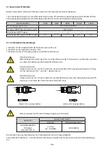
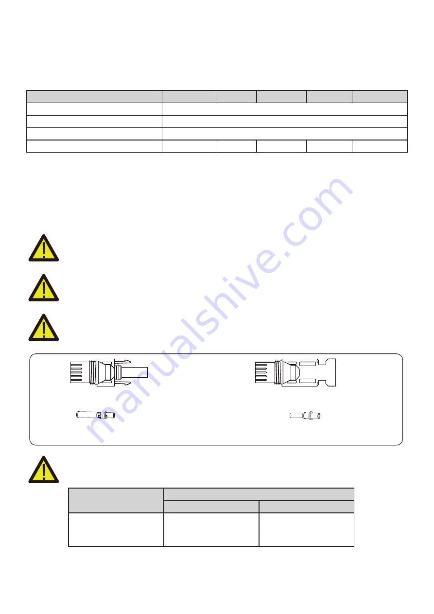
Pic 5.1 DC+ male connector (MC4)
Pic 5.2 DC- female connector (MC4)
PV Input Voltage
Inverter Model
PV Array MPPT Voltage Range
No. of MPP Trackers
No. of Strings per MPP Tracker
550V (160V~800V)
200V-650V
2
10KW
2+1
8KW
1+1
5KW
1+1
6KW
1+1
12KW
2+1
Bild 5.1 DC+ Stecker (MC4)
Abb. 5.2 DC- Buchse (MC4)
Kabel Art
Querschnitt (mm2)
Bereich
Empfohlener Wert
Industrieübliches
PV-Kabel
(Modell: PV1-F)
4.0~6.0
(12~10AWG)
4.0(12AWG)
Die Schritte zum Zusammenbau der DC-Steckverbinder sind wie folgt aufgeführt:
a) Das Gleichstromkabel ca. 7 mm abisolieren, die Überwurfmutter des Steckers demontieren (siehe Abbildung
5.3).

