15
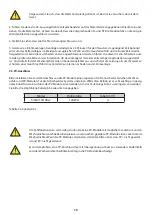
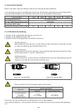
b) Crimpen von Metallklemmen mit einer Crimpzange wie in Abbildung 5.4 gezeigt.
c) Stecken Sie den Kontaktstift in das Oberteil des Steckers und schrauben Sie die Überwurfmutter auf das Oberteil
Teil des Steckers. (wie in Abbildung 5.5 gezeigt).
d) Stecken Sie schließlich den DC-Stecker in den positiven und negativen Eingang des Wechselrichters, wie in Ab-
bildung 5.6
- 15 -
Safety Hint:
Please use approved DC cable for PV system.
Cable type
Range
Recommended value
Cross section
(mm )
Industry generic PV cable
(model: PV1-F)
4.0~6.0
(12~10AWG)
4.0(12AWG)
The steps to assemble the DC connectors are listed as follows:
a) Strip off the DC wire about 7mm, disassemble the connector cap nut (see picture 5.3)
.
b) Crimping metal terminals with crimping pliers as shown in picture 5.4.
c) Insert the contact pin to the top part of the connector and screw up the cap nut to the top
part of the connector. (as shown in picture 5.5).
Pic 3.3 Disassemble the connector cap nut
7mm
7mm
Pic 3.4 Crimp the contact pin to the wire
Chart 3-6
- 16 -
Pic 3.5 connector with cap nut screwed on
d) Finally insert the DC connector into the posi�ve and nega�ve input of the inverter, shown as
picture 5.6
Pic 3.6 DC input connec�on
Warning:
Sunlight shines on the panel will generate voltage, high voltage in series may
cause danger to life. Therefore, before connec�ng the DC input line, the solar
panel needs to be blocked by the opaque material and the DC switch should
be 'OFF', otherwise, the high voltage of the inverter may lead to life-
threatening condi�ons.
Warning:
Use the DC power connector of the accessories. Do not interconnect the
connectors of different manufacturers.
Warnung:
Wenn Sonnenlicht auf das Panel scheint, wird eine Spannung erzeugt, die zu einer lebensgefähr-
lichen Hochspannung in der Serie führen kann. Daher muss das Solarpanel vor dem Anschluss
der DC-Eingangsleitung mit einem lichtundurchlässigen Material abgedeckt werden und der
DC-Schalter sollte auf „OFF“ stehen, da sonst die hohe Spannung des Wechselrichters zu lebens-
gefährlichen Zuständen führen kann. Bedingungen führen.
Verwenden Sie den Gleichstromanschluss des Zubehörs. Verbinden Sie nicht die Steckverbinder
verschiedener Hersteller.
- 08 -
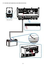
Please follow below steps to implement ba�ery connec�on:
1. Please choose a suitable ba�ery cable with correct connector which can well fit into the
ba�ery terminals. 2. Use a suitable screwdriver to unscrew the bolts and fit the ba�ery
connectors in, then fasten the bolt by the screwdriver, make sure the bolts are �ghtened
with torque of 24.5 N.M.
2. Nm in clockwise direc�on, make sure polarity at both the ba�ery and inverter is correctly
connected.
Connec�ng the ba�ery with a suitable cable is important for safe and efficient
opera�on of the system. To reduce the risk of injury, refer to Chart 3-2 for
recommended cables.
All wiring must be performed by a professional person.
3. In case of children touch or insects go into the inverter, Please make sure the inverter
connector is fasten to waterproof posi�on by twist it clockwise.
Before making the final DC connec�on or closing DC breaker/disconnect, be sure
posi�ve(+) must be connect to posi�ve(+) and nega�ve(-) must be connected to
nega�ve(-). Reverse polarity connec�on on ba�ery will damage the inverter.
Installa�on must be performed with care.
For 3.6KW/5KW model, ba�ery connector screw size: M6

