33
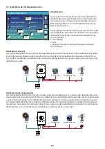
Solarverkauf:
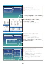
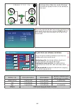
„Solarverkauf“ ist für Null-Export an die Last oder Null-Export an den Stromwandler: Wenn dieses
Element aktiv ist, kann die überschüssige Energie zurück ins Netz verkauft werden. Wenn diese Option aktiviert ist,
wird die PV-Stromquelle vorrangig wie folgt genutzt: Verbrauch unter Last, Laden der Batterie und Einspeisung ins
Netz.
Max. Leistung verkaufen:
Erlaubt die maximale Ausgangsleistung, die in das Netz fließt.
Null-Export-Leistung:
Für den Null-Export-Modus wird die Ausgangsleistung ins Netz angegeben. Es wird emp-
fohlen, diesen Wert auf 20-100 W einzustellen, um sicherzustellen, dass der Hybrid-Wechselrichter keinen Strom
ins Netz einspeist.
Energie-Muster:
Priorität der PV-Energiequelle.
Batt zuerst:
Die PV-Leistung wird zuerst zum Laden der Batterie und dann zur Versorgung der Verbraucher ver-
wendet. Wenn die PV-Leistung nicht ausreicht, wird das Netz gleichzeitig die Batterie und die Last versorgen.
Last zuerst:
Der PV-Strom wird zuerst zur Versorgung der Last und dann zum Laden der Batterie verwendet. Wenn
die PV-Leistung nicht ausreicht, wird das Netz gleichzeitig die Batterie und die Last versorgen.
Max Solar Power:
erlaubt die maximale DC-Eingangsleistung.
Netzspitzenabschaltung:
Wenn diese Funktion aktiviert ist, wird die Netzausgangsleistung auf den eingestellten
Wert begrenzt. Wenn die Lastleistung den zulässigen Wert überschreitet, werden PV-Energie und Batterie als Er-
gänzung verwendet. Wenn die Lastanforderungen immer noch nicht erfüllt werden können, wird die Netzleistung
erhöht, um die Lastanforderungen zu erfüllen.
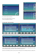
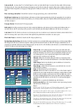
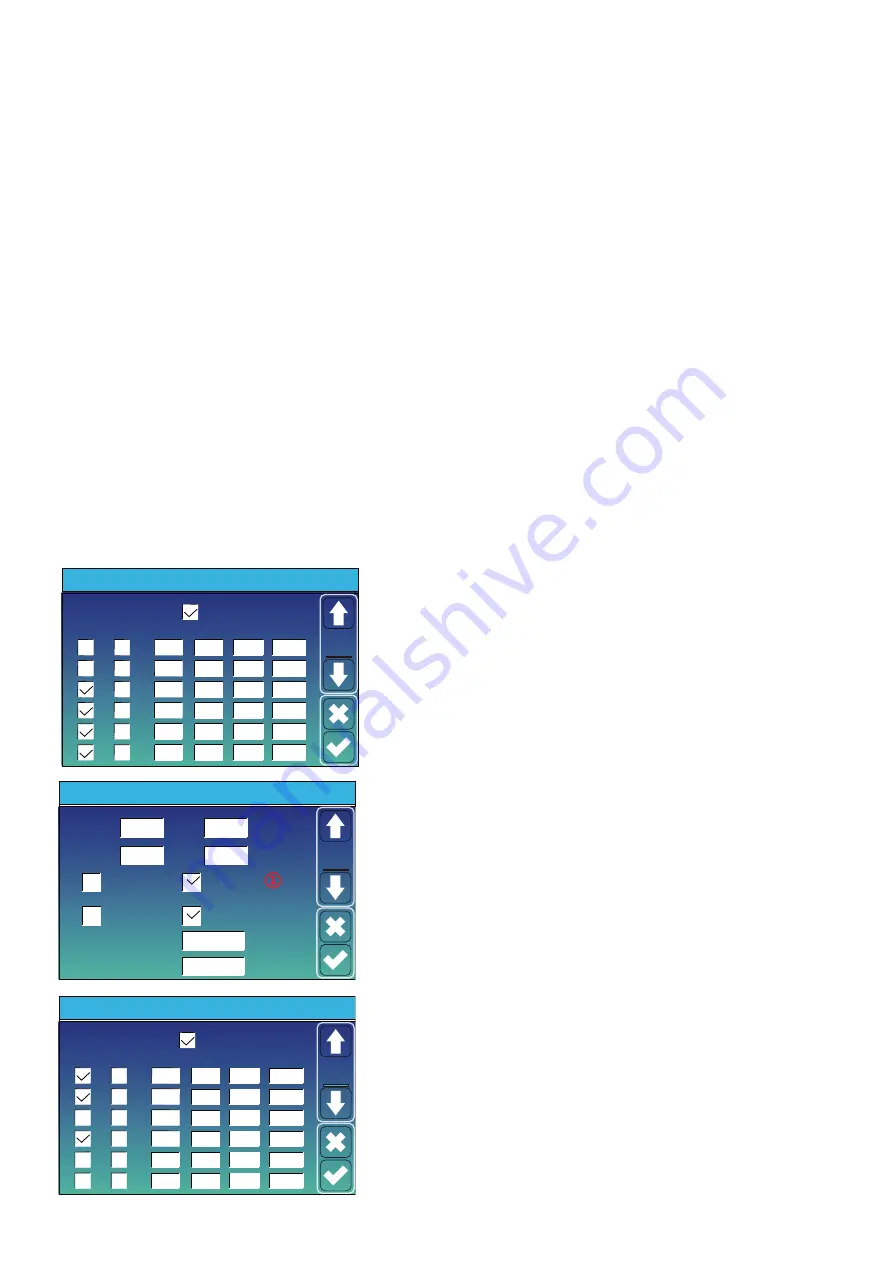
Time of use
: Hier wird programmiert, wann das Netz oder der
Generator zum Laden der Batterie verwendet wird und wann die
Batterie entladen wird, um die Last zu betreiben. Klicken Sie nur
auf „Nutzungszeit“, dann werden die folgenden Punkte (Netz,
Ladung, Zeit, Leistung usw.) wirksam.
Hinweis
: Wenn Sie im ersten Verkaufsmodus sind und auf „Nut-
zungszeit“ klicken, kann der Batteriestrom in das Netz eingespeist
werden.
Grid charge:
Nutzen Sie das Netz, um die Batterie in einem be-
stimmten Zeitraum aufzuladen.
Gen charge
: nutzen Diesel-Generator, um die Batterie in einem
me Zeitraum zu laden.
Time
: Echtzeit, Bereich von 01:00-24:00.
Hinweis:
Wenn das Netz vorhanden ist, ist nur die „Nutzungszeit“
angekreuzt, dann wird die Batterie entladen. Andernfalls wird die
Batterie nicht entladen, auch wenn der SOC der Batterie voll ist.
Im netzunabhängigen Modus (wenn das Netz nicht verfügbar ist,
arbeitet der Wechselrichter automatisch im netzunabhängigen
Modus).
POWER
: Max. erlaubte Entladeleistung der Batterie.
Batt(V oder SOC %):
SOC % der Batterie oder Spannung, bei der
die Aktion stattfinden soll.
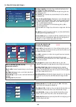
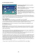
Beispiel:
In der Zeit von 01:00-05:00 Uhr, wenn der SOC-Wert der Batterie unter 80 % liegt, wird die
Batterie über das Stromnetz geladen, bis der SOC-Wert der Batterie 80 % erreicht.
Zwischen 05:00-08:00 und 08:00-10:00, wenn der SOC der Batterie höher als 40% ist, ent-
lädt der Hybrid-Wechselrichter die Batterie, bis der SOC 40% erreicht.
Wenn der SOC-Wert der Batterie zwischen 10:00 und 15:00 Uhr über 80 % liegt, entlädt der
Hybrid-Wechselrichter die Batterie, bis der SOC-Wert 80 % erreicht.
Wenn der SOC-Wert der Batterie zwischen 15:00 und 18:00 Uhr höher als 40% ist, entlädt
der Hybrid-Wechselrichter die Batterie, bis der SOC-Wert 40% erreicht.
Wenn der SOC-Wert der Batterie zwischen 18:00 und 01:00 Uhr höher als 35 % ist, entlädt
der Hybrid-Wechselrichter die Batterie, bis der SOC-Wert 35 % erreicht hat.
- 34 -
Time of use:
it is used to program when to use grid or
generator to charge the ba�ery, and when to discharge
the ba�ery to power the load. Only �ck "Time Of Use"
then the follow items (Grid, charge, �me, power etc.)
will take effect.
Note:
when in selling first mode and click �me of use,
the ba�ery power can be sold into grid.
Grid charge:
u�lize grid to charge the ba�ery in a �me
period.
Gen charge:
u�lize diesel generator to charge the ba�ery
in a �me period.
Time:
real �me, range of 01:00-24:00.
Note:
when the grid is present, only the “�me of use”
is �cked, then the ba�ery will discharge. Otherwise,
the ba�ery won’t discharge even the ba�ery SOC is
full. But in the off-grid mode (when grid is not
available, inverter will work in the off-grid mode
automa�cally).
Power:
Max. discharge power of ba�ery allowed.
Ba�(V or SOC %):
ba�ery SOC % or voltage at when the
ac�on is to happen.
Time Of Use
Time
System Work Mode
Batt
Grid
Charge Gen
01:00
05:00
09:00
13:00
17:00
21:00
5:00
9:00
13:00
17:00
21:00
01:00
Power
12000
12000
12000
12000
12000
12000
49.0V
50.2V
50.9V
51.4V
47.1V
49.0V
Work
Mode2
For example
During 01:00-05:00,
if ba�ery SOC is lower than 80%, it will use grid to charge the
ba�ery un�l ba�ery SOC reaches 80%.
During 05:00-08:00,
if ba�ery SOC is higher than 40%, hybrid inverter will discharge
the ba�ery un�l the SOC reaches 40%. At the same �me,
if ba�ery SOC is lower than 40%, then grid will charge the
ba�ery SOC to 40%.
During 08:00-10:00,
if ba�ery SOC is higher than 40%, hybrid inverter will discharge
the ba�ery un�l the SOC reaches 40%.
During 10:00-15:00,
when ba�ery SOC is higher than 80%, hybrid inverter will
discharge the ba�ery un�l the SOC reaches 80%.
During 15:00-18:00,
when ba�ery SOC is higher than 40%, hybrid inverter will discharge
the ba�ery un�l the SOC reaches 40%.
During 18:00-01:00,
when ba�ery SOC is higher than 35%, hybrid inverter will discharge
the ba�ery un�l the SOC reaches 35%.
Solar Sell:
“Solar sell” is for Zero export to load or Zero export to CT: when this item is ac�ve, the surplus
energy can be sold back to grid. When it is ac�ve, PV Power source priority usage is as follows: load
consump�on and charge ba�ery and feed into grid.
Max. sell power:
Allowed the maximum output power to flow to grid
.
Zero-export Power:
for zero-export mode, it tells the grid output power. Recommend to set it as 20-100W
to ensure the hybrid inverter won' t feed power to grid.
Energy Pa�ern:
PV Power source priority.
Ba� First:
PV power is firstly used to charge the ba�ery and then used to power the load. If PV power is
insufficient, grid will make supplement for ba�ery and load simultaneously.
Load First:
PV power is firstly used to power the load and then used to charge the ba�ery. If PV power is
insufficient, Grid will provide power to load.
Max Solar Power:
allowed the maximum DC input power
.
Grid Peak-shaving:
when it is ac�ve, grid output power will be limited within the set value. If the load
power exceeds the allowed value, it will take PV energy and ba�ery as supplement. If s�ll can’t meet the
load requirement, grid power will increase to meet the load needs.
Grid Charge
Gen Charge
Grid Signal
Gen Signal
Gen Max Run Time
0.0 hours
Gen Down Time
0.5 hours
Battery Setting
Start
A
30%
30%
40A
40A
Batt
Set2
Time Of Use
Time
System Work Mode
Batt
Charge Gen
01:00
05:00
08:00
10:00
15:00
18:00
5:00
8:00
10:00
15:00
18:00
01:00
Power
80%
40%
40%
100%
40%
35%
Work
Mode2
12000
12000
12000
12000
12000
12000
Grid
②

