38
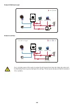
Mode IV: AC-Paar
Mode III: Mit Smart-Load
7. Limita�on of Liability
In addi�on to the product warranty described above, the state and local laws and regula�ons
provide financial compensa�on for the product's power connec�on (including viola�on of implied
terms and warran�es). The company hereby declares that the terms and condi�ons of the
product and the policy cannot and can only legally exclude all liability within a limited scope.
- 39 -
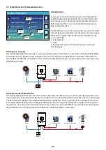
The 1st priority power of the system is always the PV power, then 2nd and
3rd priority power will be the ba�ery bank or grid according to the se�ngs.
The last power backup will be the Generator if it is available.
Grid
Backup Load
On-Grid Home Load
Battery
Solar
CT
AC cable
DC cable
Smart Load
Mode III: With Smart-Load
Grid
Backup Load
On-Grid Home Load
Battery
Solar
On-Grid+AC couple
AC cable
DC cable
On-Grid Inverter
Mode IV: AC Couple
CT
The 1st priority power of the system is always the PV power, then 2nd and 3rd priority power will
be the battery bank or grid according to the settings. The last power backup will be the Generator
if it is available.
- 08 -
Please follow below steps to implement ba�ery connec�on:
1. Please choose a suitable ba�ery cable with correct connector which can well fit into the
ba�ery terminals. 2. Use a suitable screwdriver to unscrew the bolts and fit the ba�ery
connectors in, then fasten the bolt by the screwdriver, make sure the bolts are �ghtened
with torque of 24.5 N.M.
2. Nm in clockwise direc�on, make sure polarity at both the ba�ery and inverter is correctly
connected.
Connec�ng the ba�ery with a suitable cable is important for safe and efficient
opera�on of the system. To reduce the risk of injury, refer to Chart 3-2 for
recommended cables.
All wiring must be performed by a professional person.
3. In case of children touch or insects go into the inverter, Please make sure the inverter
connector is fasten to waterproof posi�on by twist it clockwise.
Before making the final DC connec�on or closing DC breaker/disconnect, be sure
posi�ve(+) must be connect to posi�ve(+) and nega�ve(-) must be connected to
nega�ve(-). Reverse polarity connec�on on ba�ery will damage the inverter.
Installa�on must be performed with care.
For 3.6KW/5KW model, ba�ery connector screw size: M6


