background image


MAINTENANCE 


Warning:

  When repairing, maintaining and cleaning the machine, it is particularly important 

to be aware of the safety precautions.  Park the tractor (if connected) as a precautionary 
measure and disconnect power when servicing.  Do not clean, lubricate or adjust the machine 
before the tractor engine has been stopped and the parking brake is activated. 
 

Important:

  Screws and bolts on your new machine must be tightened up after the first two 

hours of operation.  All moveable parts must be greased regularly for the best performance.  
To extend the durability of the machine, frequent and thorough cleaning is recommended.  Set 
spring tension to loosest setting for ease of cleaning the machine and use plenty of water 
when cleaning to avoid material freezing on the roller or rubber belts.   
 

Remember:

  Do not spray water directly into bearings or bearing housings.  If the machine is 

stored for a lengthy period of time, spray it with acid-free oil before use.  Remove all foreign 
material from the roller.  Check and lubricate all chain and bearings regularly. 
 

            It is important to properly maintain and service your spreader.  Failure to comply   


with the manufacturer’s suggested servicing procedures m

ay result in premature 

wear and may hinder the machine’s performance.


ATTACHMENT OF THE MACHINE 


This spreader can be attached to the tractor using various methods.  It is the operator’s 

responsibility to make sure that it is connected and fastened properly and safely.  Ensure that 
the spreader sits horizontally when in operation. 

 
Hydraulic Units:


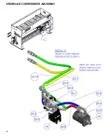
Ensure the hydraulic hoses are properly connected to the tractor’s hydraulic 

ports.  Improper connection may damage the machine if the oil runs in the wrong direction.  
Flow control and hoses to the tractor are included. 

 
Electric Units:


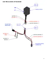
Ensure the wiring kit is properly connected to the tractor’s battery.  A w

iring kit 

is included.  See page 15 for connection diagram. 


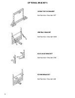
Mounting options include 3 Point Hitch bracket, Ventrac bracket, Click-N-Go bracket and 
Steiner bracket.  See page 16 for an illustration of these brackets. 


Summary of Contents for 440E

Page 1: ...BAUMAN MANUFACTURING 440E 440H DROP SPREADER OPERATOR S MANUAL...

Page 2: ...DOCUMENT REVISION DECEMBER 2018 MODEL SERIAL NUMBER PURCHASE DATE DEALER WHERE PURCHASED 3 INDUSTRIAL DRIVE ELMIRA ON N3B 2S1 PHONE 519 669 4333 FAX 519 669 2431 WWW BAUMANMFG COM...

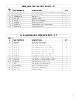
Page 3: ...READING MATERIAL 7 HYDRAULIC ELECTRICAL ROUTING INSTRUCTIONS 7 440E 440H COMMON PARTS LIST 8 440E ELECTRIC SPECIFIC PARTS LIST 9 440H HYDRAULIC SPECIFIC PARTS LIST 9 INSTALLATION LOCATIONS 10 HYDRAULI...

Page 4: ...includes following the factory s preparation operation and maintenance instructions This manual will help you understand the proper maintenance and operation of the spreader in order to maximize the...

Page 5: ...aulic components are not subjected to continuous operating pressure exceeding 1800 psi or intermittent pressures of 2350 psi A higher pressure may cause danger of exploding parts hot oil exposure or c...

Page 6: ...chine to the ground when parked Disconnect power before servicing Do not work underneath an elevated unit until it has been secured mechanically or with stop wedges Do not start or operate the tractor...

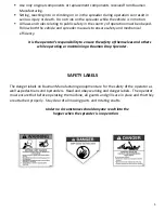
Page 7: ...nd mechanical efficiency It is the operator s responsibility to ensure the safety of themselves and others while operating or maintaining a Bauman Drop Spreader SAFETY LABELS The danger labels on Baum...

Page 8: ...with acid free oil before use Remove all foreign material from the roller Check and lubricate all chain and bearings regularly It is important to properly maintain and service your spreader Failure t...

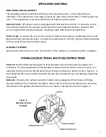
Page 9: ...may be installed allowing for fine tuning of the motor rotation speed STARTING TO SPREAD Spreading of material starts as soon as the tractor s PTO hydraulic or electrical system is engaged HYDRAULIC E...

Page 10: ...0 DOUBLE SPROCKET 1 11 1140 411 40 ROLLER CHAIN WITH C LINK DRUM 1 12 440 200 440 GRILL 1 13 440 305 TENSION LEVER FOR 440 1040SI 1 14 440 100 HOPPER WELDMENT 1 15 DECAL BAUMAN LOGO 12 BAUMAN LOGO 12...

Page 11: ...440H 1 33 1 HYD FLOW FLOW CONTROL VALVE 8GPM 1 33 2 HYD6602 6 6 6 SWIVEL NUT RUN TEE MJIC x MJIC x FJIC 1 33 3 HYD6801 6 8 STRAIGHT THREAD ELBOW MJIC x MORB 90 2 33 4 HYD6400 6 8 STRAIGHT THREAD CONN...

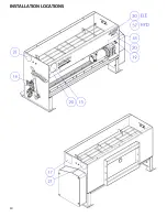
Page 12: ...10 INSTALLATION LOCATIONS...

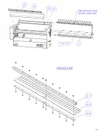
Page 13: ...11...

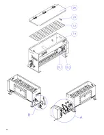
Page 14: ...12...

Page 15: ...13...

Page 16: ...14 HYDRAULIC COMPONENTS ASSEMBLY...

Page 17: ...15 ELECTRICAL HOOK UP DIAGRAM...

Page 18: ...16 OPTIONAL BRACKETS 3 POINT HITCH BRACKET Part Number Bracket 3 PT VENTRAC BRACKET Part Number Bracket 4100 CLICK N GO BRACKET Part Number Bracket CNG STEINER BRACKET Part Number Bracket 440...

Page 19: ...17 ADDITIONAL OPTIONS GALVANIZED METAL LID Part Number 440 LID SOFT COVER Part Number 440 COVER CONTROL BLOCK VARIABLE POWER Part Number 1801 440 80A SC...

Page 20: ...s where a failure could result in a costly dangerous or life threatening situation Bauman Manufacturing will not be held responsible for damages or losses greater than the cost of the Bauman Manufactu...

Page 21: ...19 NOTES...

Page 22: ...20...

Page 23: ...21...

Page 24: ...22...

Reviews: