background image


6

EN

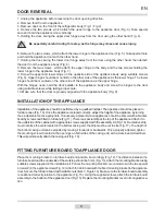
DOOR REVERSAL

1. Unplug the appliance before reversing the door opening direction.

2. Remove food from the appliance.

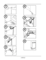
3. Remove caps on the front of the refrigerator body (Fig. 1, Fig 2).

4. Remove the two screws, which attach the upper hinge to the appliance door (Fig. 3). Take special 

care and hold the appliance door vertically.

5. Holding the door, swing the upper door hinge away from the door using the other hand (Fig. 4).

Be especially careful during this step, as the hinge may close and cause injury.

6. Remove the two screws, which attach the lower hinge to the appliance door (Fig. 5). Take special care 

and hold the appliance door with the other hand.

7. Holding the door, swing the lower door hinge away from the door using the other hand, then detach 

the door from the appliance body (Fig. 6).

8. Remove the two screws , which attach the upper hinge to the body and the two screws holding the 

lower hinge to the appliance body (Fig. 7).

9. Screw the upper and lower hinge on the opposite side of the appliance body using suitable screws 

(Fig. 8). Upper hinge should be mounted on the other side of the appliance as the lower hinge. The lower 

hinge should be mounted on the other side of the appliance as the upper hinge.

With the hinges open, hold the door parallel to the appliance body and screw the hinges to the door 

using suitable screws while taking proper care.

10. Make sure that the door is properly aligned with the appliance body (Fig. 9).

INSTALLATION OF THE APPLIANCE

Installation of the appliance should be performed by a qualified installer. The appliance should be placed in 

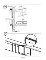
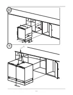
furniture case (Fig. 10). Once the appliance is placed correctly, adjust the height of the appliance by turning 

the 4 adjustable feet as appropriate. If necessary, adjacent Amica appliances should be braced with a bracket 

fixed by screws and fitted in furniture (Fig. 11). There is a special strip at the top of the appliance. Attach it to 

the underside of the cabinet with appropriate screws supplied with the assembly kit (Fig. 16). Decorative strip 

must not block the vents located in the bottom casing unit, the strip must be cut to size (Fig. 17). The depth of 

the bottom casing unit can be adjusted by moving it forwards or backwards. Once properly adjusted, tighten 

the mounting screws (located in the openings on both sides of the casing unit) with a cross-head screwdriver. 

This will permanently attach the casing unit (Fig. 18).

FITTING FURNITURE BOARD TO APPLIANCE DOOR

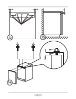
  Place the mounting bracket on furniture board and position it accordingly (Fig. 12). The distance between the 

furniture board and the underside of the worktop should be 5 mm (Fig. 13). Attach the mounting bracket using 

suitable screws supplied in the installation kit. Pull out the mounting bracket cover and screw in the two special 

screws (2) in the appliance doors(Fig. 14). Attach furniture board with the fixed mounting bracket to the appliance 

door. Secure the furniture board with suitable nuts (item 3, Figure 14). Make sure the furniture board assembly 

is positioned correctly relative to the appliance (Fig. 15). Using the supplied screws, attach the furniture board 

assembly to the bottom of the appliance door (Fig. 15). Replace the mounting bracket cover in its original loca-

tion.

Summary of Contents for BR100

Page 1: ...BR100 Built under refrigerator with freezer compartment ...

Page 2: ...Built under Refrigerator Instruction Manual BR100 MODEL ...

Page 3: ...ration instillation 4 5 Operation 6 Instruction 7 10 Defrosting cleaning and de commissioning 11 12 Trouble shooting 13 Door Appliance installation 14 19 Important information 20 Technical Data 21 Baumatic consumables 22 Contact details 24 ...

Page 4: ... of your new appliance may be disposed without any danger to the environment The cardboard box may be broken or cut into smaller pieces and given to a waste paper disposal service The wrapping foil is made of polyethylene and the polyethylene pads and stuffing contain no fluorochloric hydrocarbon All these valuable materials may be taken to a waste collecting center and used again after adequate r...

Page 5: ...2 ...

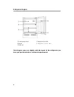
Page 6: ...Freezing compartment 2 Temperature Controller 3 Shelves 4 E g g t r a y d o o r r a c k 5 Bottle rack This diagram may vary slightly with the layout of the refrigerator you have just purchased due to technical improvements 3 ...

Page 7: ... has been sited and cleaned let it stand for more than 30 minutes before connecting the power source Ventilation Level the appliance with a spirit level and a try square The appliance has adjustable feet A minimum gap of 38mm must be maintained at the back of the appliance for ventilation Do not cover the air inlet at the front of the appliance and allow for 200cm air flow through plinth Check the...

Page 8: ...prox 10mm between the lower front frame and bottom board of the kitchen Fix lower mountings 3 to the lower front frame with screws 2 Fix the lower mountings to the bottom board of the kitchen unit with screws 2 5 Properly insert seals in the apertures on the left upper and right sides of the refrigerator 6 Fix the door to the holders 4 each upper and lower position has one with screws 2 Press clos...

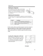
Page 9: ...temperatures the ambient temperature the frequency with which the door is opened and closed and the amount of food in storage 6 Thermostat Loading the refrigerator with food When the refrigerator is switched on do not load food until 1 2 hours have passed Usually food for cold storage or deep freezing can be loaded when the temperature inside the compartment reaches the set point Quick cooling ...

Page 10: ...s of the cold storage compartment can be regulated between 0 and 10 degrees Centigrade extended periods of food storage is not recommended Cold storage should only be used for short term storage Cold storage compartment 1 Eggs and butter 2 Beverages and bottled drink 3 Food to be frozen 4 General food meat vegitables etc ...

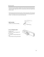
Page 11: ...ement Lamp 240V 10W Lamp holder E14 lamps exceeding 15W must not be used For replacement unplug to disconnect the power Remove the lamp by turning anti clockwise Shelves can be taken out for cleaning Shelf cleaning ...

Page 12: ...9 ...

Page 13: ...10 ...

Page 14: ...11 ...

Page 15: ...12 ...

Page 16: ...13 Light does not switch on ...

Page 17: ...ld be performed by a qualified installer The appliance should be placed in furniture case Fig 10 Once the appliance is placed correctly adjust the height of the appliance by turning the 4 adjustable feet as appropriate If necessary adjacent Amica appliances should be braced with a bracket fixed by screws and fitted in furniture Fig 11 There is a special strip at the top of the appliance Attach it ...

Page 18: ...1 1 2 3 4 5 8 9 6 7 ...

Page 19: ...19 596 820 870 158 208 525 25 600 600 550 540 596 596 5 1200 10 11 ...

Page 20: ...3 5 15 15 9mm 3 2 14 12 13 ...

Page 21: ...4 15 16 ...

Page 22: ...5 18 17 ...

Page 23: ...st of the call out charge The appliance must be accessible for the engineer to perform any necessary repair If your appliance is installed in such a way that an engineer is concerned that damage will be caused to the appliance or your kitchen then he will not complete a repair This includes situations where appliances have been tiled in sealed in with sealant have wooden obstructions placed in fro...

Page 24: ...ents Temperature Rise Time 11 hours Freezing Capacity 2kg 24hr Climate Class 3 N ST Noise Level 41 dB Installation Type Built under 1 On a scale from A highest efficiency to G lowest efficiency 2 Annual energy consumption based on standard test results for 24 hours The actual energy consumption will depend on how the appliance is used and where it is located 3 This appliance is intended to be used...

Page 25: ...g o BC003 Ceramic Hob Cleaner 250 ml o BC004 Oven Cleaner 250 ml o BC005 Stainless Steel Cleaner and Protector 250 ml o BC007 E Cloth General Purpose Cloth o BC008 Microwave Cover To order a Baumatic consumable product please call 0123 5437 244 and quote the product code You can also order online from eshop baumatic co uk ...

Page 26: ......

Page 27: ...w facebook com baumatic uk Republic of Ireland Service Telephone 1 890 812 724 Spares Telephone 091 756 771 Czech Republic Baumatic CR spol s r o Lípovà 665 460 01 Liberec 4 Czech Republic 420 483 577 200 www baumatic cz Slovakia Baumatic Slovakia s r o Panenská 34 811 03 Bratislava Staré Mesto Slovakia 421 255 640 618 www baumatic sk Germany Baumatic Gmbh Bachstr 10 12 D 32 257 Bünde Deutschland ...

Page 28: ...18 ...
Reviews: