


MB053 - 11055655
Baumer_EEXGP02-TG74D_II_DE-EN (18A1)
2
General notes
1
1
General notes
1.1
Symbol guide:
Danger
Warnings of possible danger
General information for attention
Informations to ensure correct device operation
i
Information
Recommendation for device handling
1.2
The
tachogenerator with EX approval EExGP 0,2 • TG 74 d
is a
generator-based working
precision rotary measurement device
which must be handled with care by skilled
personnel only.
1.3
The expected
service life
of the device depends on the
ball bearings
, which are equipped with
a permanent lubrication.
1.4
The expected
service life
of
carbon brushes
depends on the electrical current and is usually
consistent with the service life of the ball bearings. Replacement of the carbon brushes is only a
recommended precaution.
1.5
The
storage temperature range
of the device is between -15 °C and +70 °C.
1.6
In Ex areas 2 G the device must only be used within the
ambient temperature range
from -20 °C to +55 °C.
1.7
EU Declaration of Conformity
meeting to the European Directives.
1.8
We grant a
2-year warranty
in accordance with the regulations of the ZVEI (Central Association
of the German Electrical Industry).
1.9
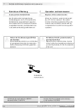
Maintenance work
is not necessary.
Repair work
must be carried out by the
manufacturer
.
Alterations of the device are not permitted.
Contravention invalidates the EX approval.
1.10
In the event of
queries
or
subsequent deliveries
, the data on the device type label must be
quoted, especially the type designation and the serial number.
1.11
Device components are to be
disposed
of according to the
regulations prevailing in the
respective country
.
i
Warning!
Damaging the seal
on the device invalidates warranty.


