Manual_PROFINET_EN.doc 13/24
www.baumer.com
17.10.11
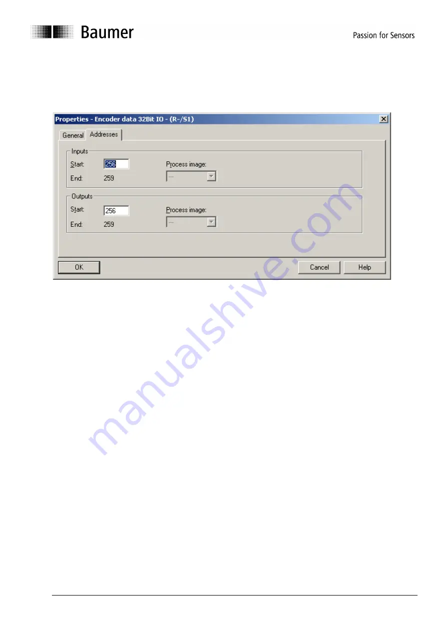
5.4. Assigning I/O addresses to input and output data
The input and output data must be assigned I/O addresses to enable later access by the control software.
Click on the encoder image in HW config of Step7 to select the encoder. Then double-click on module
“encoder data 32 bit I/O (plug-in 1) at left below, opening the window “Properties – RT encoder data 32 bit
IO” with tab “Addresses” (see screenshot).
Enter the beginning of the respective address or adopt the automated proposal. Identical or overlapping
addresses for input and output are admissible.
5.5. Real Time Class Selection
The encoder supports the three PROFINET real time classes Realtime (RT), Isochrone Realtime (IRT)
Class2 and Class3. Which real time class is used best, depends on the demands of your application and thus
on the controller used (i.e. on the PLC).
5.5.1. Realtime (RT) Class 1
Realtime with a typical cycle time of 100ms or less. Standard network components (interfaces, switches) may
be used.
5.5.2. Isochrone Realtime (IRT) Class 2
Realtime without topology planning. Typical cycle time 10ms or less. All network components must support
PROFINET IRT frame priority processing
5.5.3. Isochrone Realtime (IRT) Class 3
Realtime with topology planning. Typical cycle time 1ms or less. All network components must support
PROFINET IRT frame priority processing.
Position values are captured with an accuracy of +/- 1µs or better, with respect to the highly accurate bus
clock.
Domain Management
An IRT Class3 Device must be member of a Sync-Domain. The Sync Domain is provided by the
Sync-Master, which usually is the controller. Enter the properties of the Sync Domain here, especially
the cycle time of the send clock. Only those values may be entered which are common to both the
master and all devices on bus.
Enter the Domain-Management e.g. by right-clicking the PROFINET bus rail in the Hardware window
of Step7 software.


