background image

NE210

www.baumer.com

33

Operating modes
Adding mode

In adding mode the programmed preset „P“ is reached by counting 

up. The signal output (final contact) is triggered as soon as actual va-

lue and preset are identical. Any external, manual or automatic reset 

will make the counter reset to zero or to a programmed offset value.

Subtracting mode

In subtracting mode the programmed preset „P“ is reached by coun-

ting down. The signal output (final contact) is triggered by zero or a 

programmed offset value.

No matter what counting mode has been defined, the incoming 

impulses may be added or subtracted. For more details please refer 

to chapter 5.1 Counting modes.  

In the case of two counting signals, phase offset by 90° and with 

fourfold evaluation, the maximum counting frequency reduces to  

5 kHz.

3.7  Executing the test routine

The test routine is described below.


Start test


  Press the keys 

 and 

 simultaneously and switch the 


counter on.


All the display segments will be displayed automatically in se-

quence and are thereby tested for functional capability.


Test repeat

  If you wish to repeat the test:


Press the 

 key.


Test extension

  Other counter functions can be tested:


Press the 

 key again.

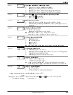
No machine functions may be connected when the outputs are 

tested.

Testing of inputs A and B and reset input R.


Inputs can be triggered simultaneously or individually. A display 

is only provided when a signal is applied.

Output test.

The output is now activated.

Reset the output with the key 

.

Testing of DIP-switches in accordance with ON/OFF settings. The 

settings and functions of the DIP-switches can be changed while 

the test is in progress.

End of test

The test routine is now terminated.

Summary of Contents for NE210

Page 1: ...zeichnung Baumer IVO GmbH Co KG Dauchinger Strasse 58 62 DE 78056 Villingen Schwenningen Phone 49 7720 942 0 Fax 49 7720 942 900 www baumer com info de baumerivo com Betriebsanleitung Elektronischer V...

Page 2: ...einwandfreiem Zustand verlassen Um diesen Ger te Status zu erhalten ist es erforderlich dass Sie das Ger t bestimmungsgem ss sicherheits und gefahrenbewusst unter Beachtung dieser Betriebsanleitung un...

Page 3: ...entsprechende Sicherheitsvorkehrungen getroffen werden ffnen Sie nicht das Geh use des Ger tes und nehmen Sie keine Ver nderungen daran vor Manipulationen am Ger t k nnen dessen Funktionssicherheit n...

Page 4: ...ige Aktueller Z hlerstand Vorwahlwert Skalierungsfaktor Bedienfeld Auswahltaste f r Programmierung und Bedienung R ckstelltaste Einstelltaste f r Dekadeneingabe Einstelltaste f r Dekadenanwahl 2 2 Blo...

Page 5: ...takt Relaiskontakt Endkontakt Relaiskontakt Signaleingang A Spur A Signaleingang B Spur B R ckstellung durch ein externes Signal Elektr Ausgang wahlweise PNP oder NPN Logik Codiereingang f r Eingangsl...

Page 6: ...ng betreiben Nach EN 61010 darf im St rungsfall 8 A 150 VA W niemals berschritten werden 3 2 Signalausg nge belegen Relaiskontakte 6 5 4 Die Anschl sse 4 5 und 6 bilden einen potentialfreien Umschalt...

Page 7: ...PNP Impulsgeber verwendet werden Die gew nschte Eingangslogik l sst sich an der Anschlussklemme durch eine Drahtbr cke festlegen siehe Eingangslogik festlegen Spezifikation der Eing nge Anschluss 7 H...

Page 8: ...rden PNP Ansteuerung mit positivem Signal K E B 11 und 12 13 12 11 10 9 8 7 wenn der Impulsgeber eine NPN Endstufe hat NPN Ansteuerung mit negativem Signal E K B 11 und 13 13 12 11 10 9 8 7 bei Wechse...

Page 9: ...PNP Br cke nach 0 V 12 0 V 13 24 V N herungsschalter PNP 7 Spur A 8 Spur B 9 R ckstellung 11 PNP Br cke nach 0 V 12 0 V 13 24 V N herungsschalter NPN 7 Spur A 8 Spur B 9 R ckstellung 11 NPN Br cke nac...

Page 10: ...m den Schaltstrom des elektronischen Ausgangs 3 6 Grundeinstellungen vornehmen DIP Schalter An der Geh useseite befinden sich ein DIP Schalter zur Einstellung der Haupt Ger tefunktionen Betriebsart R...

Page 11: ...g reduziert sich die maximale Z hlfrequenz auf 5 kHz 3 7 Testroutine durchf hren Hier finden Sie eine Beschreibung der Testroutine Test Start Gleichzeitig Tasten und gedr ckt halten und Ger t einschal...

Page 12: ...d ablesen R ckstellen In der Programmierebene muss eine Freigabe f r das R ckstellen Zeile 6 bestehen Taste dr cken Vorwahlwert In der Programmierebene Zeile 5 muss eine Freigabe f r den Vorwahlwert b...

Page 13: ...t Die Programmierebene ist in die Programmierfelder PRO 0 und PRO 1 gegliedert Die beiden Programmierfelder werden nun hinter einander in der realen Reihenfolge beschrieben Programmierung einschalten...

Page 14: ...zimalpunkt 0 99999 1 9999 9 2 999 99 3 99 999 Zeile 2 Wischsignalzeit in Sekunden s 0 02 bis 9 99 s einstellbar 0 00 kein Ausgangssignal 0 25 0 02 9 99 s DIP Schalter 2 schaltet Wischkontakt oder Daue...

Page 15: ...usgang schaltet bei Setzwert Zeile 9 Zeitbereich und Aufl sung 0 999 s 99 100 s 1 99 min 59 s 9 10 s 2 999 min 59 s 3 999 h 59 min Gilt nur f r Z hlweise als Zeitz hler oder Zeitrelais Zeile 10 Zeitre...

Page 16: ...tr n n 1 n 2 n 3 n 4 0 1 2 3 4 Differenzz hlung Spur A addierend Spur B subtrahie rend A B Signaldauer und Zeitpunkt beliebig Spur A Spur B Z hlung Summenz hlung Spur A und Spur B addierend A B Die Be...

Page 17: ...ang Automatische R ckstellung mit Wischsignal R ckstellung Vorwahl SetzwerW Ausgang Tw R ckstellung Vorwahl SetzwerW Ausgang Tw Externe R ckstellung mit Wischsignal R ckstellung Vorwahl SetzwerW Ausga...

Page 18: ...toppeingang Spur B Anschluss 8 beim Zeitz hler Die Dezimalpunkteinstellung in Programmierzeile 1 bleibt unwirksam Die nachstehenden Diagramme zeigen das Ausgangsverhalten in Ab h ngigkeit von den Sign...

Page 19: ...Spur B beim Zeitz hler Die programmierten Werte der Programmierzeilen 1 2 und 8 bleiben unwirksam Die nachstehenden Diagramme zeigen das Ausgangsverhalten in Ab h ngigkeit von dem Signaleingang Betri...

Page 20: ...llbar Betriebsarten Hauptvorwahl Zeitz hler Zeitrelais Datenspeicherung 10 Jahre im EEPROM R ckstellung Taste elektrisch oder automatisch Ausg nge elektronisch NPN PNP Schalttransistor Ausg nge Relais...

Page 21: ...ik Z hleingang Ansteuerstrom 9 16 mA Abschaltstrom 0 5 mA Eingangswiderstand 1 65 k R ckstelleingang Ansteuerstrom 5 8 mA Abschaltstrom 0 5 mA Eingangswiderstand 3 3 k Relais Ausgang Ausgangsschaltung...

Page 22: ...Vorwahl nderung Wirksam nach R ckstellung C Taste Aktiv 6 3 Fehlermeldungen Fehler muss im Werk behoben werden Fehler muss im Werk behoben werden Z hlfrequenz ber 10 kHz Nach Netzausfall Z hlerstandsa...

Page 23: ...28 Assignment electronic output 29 Assignment signal input 29 Typical connections 31 Connecting the sensor supply 32 Establishing basic settings 32 Executing the test routine 33 Operating mode 34 Prog...

Page 24: ...ate and in safe condition To keep the units in this condition it is necessary that the units be installed and operated properly in a safety and hazard conscious manner under observance of this operati...

Page 25: ...sks or a danger of property or environmental damage could result then appropriate safety precautions must be taken Do not open the housing of the units or make any changes to it Tampering with the uni...

Page 26: ...des LED display Current main counter Preset value Scalling factor Control panel Selector key for programming and operating Reset key Setting key for decade values Setting key for decades selection 2 2...

Page 27: ...tact Signal output relay contact Signal input A track A Signal input B track B Reset by external signal Electronic output choice of PNP or NPN logic Coding input for input logic Sensor supply Sensor s...

Page 28: ...A W must never be exceeded in the event of a fault 3 2 Assignment signal output relay contact 6 5 4 Terminals 4 5 and 6 form a no potential changeover contact which can be assigned as a pulse or conti...

Page 29: ...iggered by any PNP or NPN encoder The required input logic can be assigned at the connecting terminal by wire jumper refer also to assigning the input logic Specification of the inputs Terminal 7 Main...

Page 30: ...erator PNP triggered by a plus signal K E B 11 and 12 13 12 11 10 9 8 7 If the pulse generator has an NPN output stage NPN triggered by a minus signal E K B 11 and 13 13 12 11 10 9 8 7 In conjunction...

Page 31: ...ck B 9 reset 11 PNP jumper to 0 V 12 0 V 13 24 V Proximity switch PNP 7 track A 8 track B 9 reset 11 PNP jumper to 0 V 12 0 V 13 24 V Proximity switch NPN 7 track A 8 track B 9 reset 11 NPN jumper to...

Page 32: ...ng current of the electronic output 3 6 Establishing basic settings DIP switches The housing provides at rear four DIP switches to specify the main basic device functions such as operating mode kind o...

Page 33: ...tion the maximum counting frequency reduces to 5 kHz 3 7 Executing the test routine The test routine is described below Start test Press the keys and simultaneously and switch the counter on All the d...

Page 34: ...he operating mode Read the counter status display Reset Resetting must be enabled in the programming mode line 6 Press the key Preset value Functions relating to the preset value must be enabled in th...

Page 35: ...rameters are set in the programming mode which is subdivided into two programming segments i e PRO 0 and PRO 1 Both segments are described below in their actual order Access programming Set DIP switch...

Page 36: ...999 9 2 999 99 3 99 999 Line 2 Pulse signal time in seconds s adjustable from 0 02 s to 9 99 s 0 00 no output signal 0 25 s 0 02 9 99 s DIP switch 2 activates pulse contact of continuous contact Line...

Page 37: ...ch 1 ON output set to start count value Line 9 Time scale and resolution 0 999 s 99 100 s 1 99 min 59 s 9 10 s 2 999 min 59 s 3 999 h 59 min Only applicable to use as a time counter or time delay rela...

Page 38: ...0 1 2 3 4 Differential counting track A adding track B subtracting A B Any signal duration and time Track A Track B Counting Totalizing tracks A and B adding A B The operating mode and con sequent co...

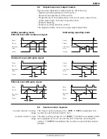
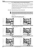
Page 39: ...nses Adding operating mode External reset with continuous signal Subtracting operating mode Automatic reset with pulse signal External reset with pulse signal Reset Preset Start count value Output Tw...

Page 40: ...ting direction are selected with DIP switch 1 Resetting with a pulse signal or continuous signal is effected with DIP switch 2 Start input Track A terminal 7 in time counting mode Stop input Track B t...

Page 41: ...of the positions of the DIP switches Start input Track A in time delay relay mode Stop output Track B in time delay relay mode The values programmed in lines 1 2 and 8 remain ineffective The diagrams...

Page 42: ...modes Main preset Time meter time relay Data memory 10 years in EEPROM Reset Button electric or automatic Outputs electronic NPN PNP transistor switch Outputs relay Potential free change over contact...

Page 43: ...c Count input Trigger current 9 16 mA Switch off current 0 5 mA Input resistance 1 65 k Reset input Trigger current 5 8 mA Switch off current 0 5 mA Input resistance 3 3 k Relay output Output circuit...

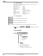
Page 44: ...set Enabled Change of preset Effective after reset C key Activated 6 3 Error messages Fault must be rectified by the factory Fault must be rectified by the factory Counting frequency above 10 kHz Afte...

Reviews: