background image

03.13 

 171.55.332/1 

 81072483

Irrtum sowie Änderungen in

 Technik und Design vorbehalten.

Subject to modifcation in technic & design. 

Sauf erreurs et sous réserve de 

modifications techniques et design.

Baumer IVO GmbH & Co. KG

Dauchinger Strasse 58-62 

 DE-78056 Villingen-Schwenningen

Phone +49 7720 942-0 

 Fax +49 7720 942-900

www.baumer.com 

 info.de@baumerivo.com

Betriebs-
anleitung

Prozessanzeigen 
PA201

1  

2

2.1

3

3.1 

3.2 

3.3  

3.4

4  

4.1

4.2

4.3

5

5.1

6

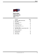
Operating 
Instructions

Process displays 
PA201

Contenu 

Page

Consignes de  
sécurité  

22

Description 

24

Caractéristiques principales  24

Raccorder l‘appareil 

24

Raccordement des conn. 

24

Entrées / sorties 

25

Alimentation  

25

Exemples de raccordements  25

Mode consultation et  
programmation 

26

Configuration de l‘entrée 

27

Configuration de l‘affichage  27

Verrouillage de la program.  27

Caractéristiques techniques  28

Dimensions 

29

Références de commande  29

Inhalt  

Seite

Allgemeines /  
Sicherheitshinweise 

2

Beschreibung 

Systembeschreibung 

Gerät anschliessen 

Anschlussbelegung 

Ein- und Ausgänge 

Betriebsspannung anschl. 

Anschlussbeispiele 

Bedienerebene -  
Programmierebene 

Eingangskonfiguration 

Anzeigen-Konfiguration 

Programmierung sperren  

Technische Daten 

Abmessungen 

Bestellbezeichnung 

9

Content 

Page

General /  
Safety instructions 

12

Description 

14

System description 

14

Connecting the device 

14

Terminal assignment 

14

Inputs and outputs 

15

Voltage supply connection 

15

Wiring examples 

15

Operating mode -  
Programming mode 

16

Input configuration 

17

Display configuration 

17

Programming lock 

17

Technical data 

18

Dimensions 

19

Part number 

19

Guide  
utilisateur

Afficheur de process 
PA201

Summary of Contents for PA201

Page 1: ...tion 26 Configuration de l entrée 27 Configuration de l affichage 27 Verrouillage de la program 27 Caractéristiques techniques 28 Dimensions 29 Références de commande 29 Inhalt Seite Allgemeines Sicherheitshinweise 2 Beschreibung 4 Systembeschreibung 4 Gerät anschliessen 4 Anschlussbelegung 4 Ein und Ausgänge 5 Betriebsspannung anschl 5 Anschlussbeispiele 5 Bedienerebene Programmierebene 6 Eingang...

Page 2: ...einwandfreiem Zustand verlassen Um diesen Geräte Status zu erhalten ist es erforderlich dass Sie das Gerät bestimmungsgemäss sicherheits und gefahrenbewusst unter Beachtung dieser Betriebsanleitung und insbesondere dieser Sicherheitshinweise installieren betreiben Stellen Sie sicher dass das Personal die Betriebsanleitung und hier besonders das Kapitel Sicherheitshinweise gelesen und verstan den h...

Page 3: ... Umweltschäden entstehen könnte n dann müssen entsprechende Sicherheitsvorkehrungen getroffen werden Manipulationen am Gerät können dessen Funktionssicherheit negativ beeinflussen und somit Gefahren hervorrufen Führen Sie keine Reparaturen am Gerät durch Schicken Sie defekte Geräte an den Hersteller zurück Installation Inbetriebnahme Bei Veränderungen einschliesslich des Betriebsverhaltens die die...

Page 4: ...ispiele vorgestellt 3 1 Anschlussbelegung HWULHEVVSDQQXQJ 3W RPPRQ 3W 7KHUPRHOHPHQW 3W 7KHUPRHOHPHQW QDORJHLQJlQJH Litzenanschluss aus Gründen des Berührungsschutzes nach EN 61010 nur mittels Aderendhülsen mit Isolierstoffkappen Vom Werk unbelegte Anschlüsse nicht anderweitig belegen Es wird empfohlen alle Sensor Anschlussleitungen abzuschirmen und die Abschirmung einseitig zu erden Beidseitige Er...

Page 5: ...gleichstellenkompensation 10 60 C Messstrom Pt100 1 3 mA Leitungswiderstand Max 40 Ω 3 3 Betriebsspannung anschliessen Es stehen verschiedene Betriebsspannungen zur Verfügung Das Gerät muss netzseitig über die empfohlene externe Sicherung betrieben werden Betriebsspannung externe Absicherung 85 265 VAC 50 60 Hz und 100 300 VDC M 100 mA 21 53 VAC 50 60 Hz und 10 5 70 VDC M 500 mA 3 4 Anschlussbeisp...

Page 6: ...Taste Ohne Funktion Programmiervorgang 1 Taste drücken Pro wird angezeigt für Einstieg in die Program mierung Nach wiederholtem Tastendruck erscheint die erste Programmierzeile Auswahl Eingangsignal 2 Die benötigten Programmierzeilen mittels der zwei Tasten und parametrieren 3 Nach der letzten Programmierzeile werden durch Drücken der Taste die Parameter automatisch gespeichert und kurz Stor angez...

Page 7: ...nheit Grad Celsius Grad Fahrenheit 4 3 Programmierung sperren Der Zutritt zur Programmierzeile Programmierung sperren erfolgt am Ende der Anzeige Konfiguration wie folgt Nach Auswahl Anzeige Einheit C oder F Taste 5 s gedrückt halten Ziffer 0 oder 1 bei LC eingeben Programmiersperre inaktiv Programmiersperre aktiv Wenn die Programmierung gesperrt ist können die Programmierzei len nur noch visualis...

Page 8: ... als overflow Anzeige Anzeigenrefresh 250 ms A D Wandler Prinzip Auflösung 16 Bit Messrate 25 s Messgenauigkeit Pt100 1 0 2 1 Digit Pt100 0 1 0 2 4 Digit Temperaturkoeff 100 ppm C Thermoelement 0 4 2 Digit Analogeingang Temperatur Pt100 Thermoelemente J K T Programmierbare Messbereich Parameter Auflösung 0 1 oder 1 C F Einheit C F Datenspeicherung 10 Jahre im EEPROM Auslegung Schutzklasse II DIN E...

Page 9: ... Schutzart DIN EN 60529 IP 65 frontseitig Bedienung Tastatur 3 Kurzhubtasten unter Frontrahmen Gehäuseart Einbaugehäuse Abmessungen B x H x L 48 x 24 x 106 mm Montageart Frontplatteneinbau mit Spannrahmen Werkstoffe Gehäuse Polycarbonat UL 94V 0 Masse ca 50 g 5 1 Abmessungen PA201 ohne Spannrahmen PA201 Spannrahmenmontage 6 Bestellbezeichnung PA201 00 AX01 Betriebsspannung 4 85 265 VAC und 100 300...

Page 10: ...PA201 10 www baumer com ...

Page 11: ...age General Safety instructions 12 Description 14 System description 14 Connecting 14 Terminal assignment 14 Inputs and outputs 15 Voltage supply connection 15 Wiring examples 15 Operating mode Programming mode 16 Input configuration 17 Display configuration 17 Programming lock 17 Technical data 18 Dimensions 19 Part number 19 ...

Page 12: ...rate and in safe condition To keep the units in this condition it is necessary that the units be installed and operated properly in a safety and hazard conscious manner under observance of this operating manual and in particular of these safety precautions Make sure that the personnel has read and understood the operating manual and in particular the Safety Instructions chapter In addition to the ...

Page 13: ... a danger of property or environmental damage could result then appropriate safety precautions must be taken Tampering with the units can have a negative affect on their opera ting safety resulting in dangers Do not make repairs on the units Return defective units to the ma nufacturer Installation commissioning In case of changes including in the operating behavior that impair safety shut down the...

Page 14: ...amples 3 1 Terminal assignment 6XSSO YROWDJH 3W RPPRQ 3W WKHUPRFRXSOH 3W WKHUPRFRXSOH QDORJ LQSXWV Litz contact only by means of connector sleeves with insulating enclosures for reasons of shock protection according to EN 61010 Do not otherwise assign contacts that have been left unassigned ex factory We recommend to screen all sensor terminal leads and to ground the shield on one side Shields on ...

Page 15: ...nalog input Cold junction compensation 10 60 C Measuring current Pt100 1 3 mA Line resistance Max 40 Ω 3 3 Voltage supply connection There are several options for operation supply Power supply must be fed in via the recommended external fuse Operating voltage External protection 85 265 VAC 50 60 Hz and 100 300 VDC M 100 mA 21 53 VAC 50 60 Hz and 10 5 70 VDC M 500 mA 3 4 Wiring examples Connection ...

Page 16: ...e in the programming line Key Without function How to program 1 Press display will switch to Pro which means access to pro gramming level Another press will make the display skip to first programming line option input signal 2 Proceed with line parameterization using keys and 3 Pressing will save the parameters after having them indicated for short The device will automatically exit the programmin...

Page 17: ...r in degrees Display unit Degrees Celsius Degrees Fahrenheit 4 3 Programming lock Accessing programming line Programming lock is after completion of display configuration by proceeding as follows Select display unit C or F and hold for 5 seconds Enter 0 or 1 in LC Programming lock disabled Programming lock enabled Programming lock means programming lines are read only which will be signaled by dAt...

Page 18: ...erflow Display refresh 250 ms A D transformer Principle Resolution 16 bit Measuring rate 25 s Measuring accuracy Pt100 1 0 2 1 digit Pt100 0 1 0 2 4 digit Temp coeffic 100 ppm C Thermocouple 0 4 2 digit Analog input Temperature Pt100 Thermocouples J K T Programmable Measuring range Parameters Resolution 0 1 or 1 C F Measuring unit C F Data memory 10 years in EEPROM Standard Protection class II DIN...

Page 19: ...54 2 5 mm2 Grid 7 62 Protection DIN EN 60529 IP 65 face Operation keypad 3 softkeys below bezel Housing type Built in housing Dimensions W x H x L 48 x 24 x 106 mm Mounting Front panel installation by clip frame Material Housing Polycarbonate UL 94V 0 Weight approx 50 g 5 1 Dimensions PA201 without clip frame PA201 clip frame mounting 6 Part number PA201 00 AX01 Voltage supply 4 85 265 VAC and 100...

Page 20: ...PA201 20 www baumer com ...

Page 21: ...ion 24 Caractéristiques principales 24 Raccorder l appareil 24 Raccordement des connecteurs 24 Entrées sorties 25 Alimentation 25 Exemples de raccordements 25 Mode consultation et programmation 26 Configuration de l entrée 27 Configuration de l affichage 27 Verrouillage de la programmation 27 Caractéristiques techniques 28 Dimensions 29 Références de commande 29 ...

Page 22: ...ueur L appareil a quitté l usine de production prêt à fonctionner et en parfait état technique vis à vis de la sécurité Afin de conserver cet état il est indispensable d installer et d utiliser l appareil conformément aux prescriptions en étant informé sur les règles de sécurité et les risques en respectant ce guide utilisateur et particulièrement les consignes de sécurité qu il contient Assurez v...

Page 23: ...entaux alors il faut prendre des mesures de sécurité correspondantes Des interventions dans l appareil peuvent avoir un effet négatif sur la sécurité de fonctionnement et par conséquent être dangereuses N effectuez aucune réparation sur l appareil Retournez l appareil dé fectueux au constructeur Installation Mise en service Suite à des modifications ou changement de comportement qui in fluencent l...

Page 24: ... raccordement ainsi que des exemples de raccordements 3 1 Connecteurs de raccordements OLPHQWDWLRQ 3W RPPXQ 3W 7KHUPRFRXSOH 3W 7KHUPRFRXSOH QWUpH DQDORJLTXH Pour se protéger contre le contact direct l extrémité des fils doit être munie d un embout de câblage isolé suivant EN 61010 Ne rien brancher sur les bornes non utilisées par le constructeur Il est recommandé de blinder toutes les lignes de ca...

Page 25: ...oudure froide 10 60 C Courant d excitation Pt100 1 3 mA Résistance des câbles Max 40 Ω 3 3 Brancher l alimentation Il existe différentes tensions d alimentation L alimentation de l appareil doit être protégée par un fusible externe dont la valeur est recommandée Alimentation Fusible externe 85 265 VAC 50 60 Hz et 100 300 VDC M 100 mA 21 53 VAC 50 60 Hz et 10 5 70 VDC M 500 mA 3 4 Exemples de racco...

Page 26: ...e message Pro s affiche pour confir mer l entrée en mode programmation En appuyant à nouveau sur la touche apparaît la première ligne de programmation Choix du signal d entrée 2 Programmer les différentes lignes à l aide des deux touches et 3 Par un appui sur la touche après la programmation des diffé rentes lignes de configuration l appareil mémorise les modifica tions en affichant le message Sto...

Page 27: ...errouillage de la programmation L accès à la ligne verrouillage de la programmation se fait à la fin de la configuration de l affichage comme suit Après avoir fait le choix entre unité d affichage C ou F appuyer et maintenir la touche pendant 5 s LC apparaît sélectionner 0 ou 1 suivant le cas Verrouillage désactivé Verrouillage activé Lorsque la programmation est verrouillée il est toujours possib...

Page 28: ...our dépasse ment de capacité d affichage Rafraîchissement d affichage 250 ms Convertisseur A D Principe Résolution 16 bit Cadence 25 s Précision Pt100 1 0 2 1 digit Pt100 0 1 0 2 4 digits Coeff de tempér 100 ppm C Thermocouple 0 4 2 Digit Entrée analogique Température Pt100 thermoelemente J K T Paramètres Echelle programmables Résolution 0 1 ou 1 C F Unité d affichage C F Mémoire 10 ans par EEPROM...

Page 29: ... pour pas 7 62 Indice de protection IP 65 en façade DIN EN 60529 Utilisation Clavier 3 Touches situées sous la face avant Type de boîtier Encastrable Dimensions L x H x P 48 x 24 x 106 mm Fixation Encastrable fixation par étrier Matière Boîtier Polycarbonate UL 94V 0 Poids 50 g 5 1 Dimensions PA201 Sans étrier PA201 Montage avec étrier 6 Références de commande PA201 00 AX01 Alimentation 4 85 265 V...

Reviews: