background image

PA210

www.baumer.com

13

Operation not covered by the specified descriptions/parameters is 

improper and can lead to 

- fatal injuries, 

- serious damage to health, 

- property damage or 

- damage to the units 

in conjunction with the systems/machines/processes to be 

controlled/monitored!

The overvoltages to which the units are subjected at the connection 

terminals must be limited to the value of the overvoltage category II 

(see Technical data)!

The units may not be operated

 -in hazardous areas,

 -as medical units,

 -in applications expressly named in EN 61010!

If the units are used to control/monitor machines or processes with 

which, as the result of a failure/malfunction or incorrect operation of 

the units 

- a life-threatening danger, 

- health risks or 

- a danger of property or environmental damage 

could result, then appropriate safety precautions must be taken!

Tampering with the units can have a negative affect on their opera-

ting safety, resulting in dangers!

Do not make repairs on the units! Return defective units to the ma-

nufacturer!

Installation/commissioning

In case of changes (including in the operating behavior) that impair 

safety, shut-down the units immediately. During installation work on 

the units, the power supply must always be disconnected. Installati-

on work may only be carried out by appropriately trained experts.

Maintenance/repairs

Always disconnect the power supply of all units involved. Main-

tenance and repair work may only be carried out by appropriately 

trained experts.

If troubleshooting is unsuccessful, do not continue to use the units.

Please contact the manufacturer in this case.

Summary of Contents for PA210

Page 1: ...nt 25 Mode consultation et programmation 26 Configuration de l affichage 27 Verrouillage de la program 27 Caractéristiques techniques 28 Dimensions 29 Références de commande 29 Inhalt Seite Allgemeines Sicherheitshinweise 2 Beschreibung 4 Systembeschreibung 4 Anzeigenbereich 4 Gerät anschliessen 5 Anschlussbelegung 5 Ein und Ausgänge 5 Betriebsspannung anschl 5 Anschlussbeispiel 5 Bedienerebene Pr...

Page 2: ...einwandfreiem Zustand verlassen Um diesen Geräte Status zu erhalten ist es erforderlich dass Sie das Gerät bestimmungsgemäss sicherheits und gefahrenbewusst unter Beachtung dieser Betriebsanleitung und insbesondere dieser Sicherheitshinweise installieren betreiben Stellen Sie sicher dass das Personal die Betriebsanleitung und hier besonders das Kapitel Sicherheitshinweise gelesen und verstan den h...

Page 3: ... Umweltschäden entstehen könnte n dann müssen entsprechende Sicherheitsvorkehrungen getroffen werden Manipulationen am Gerät können dessen Funktionssicherheit negativ beeinflussen und somit Gefahren hervorrufen Führen Sie keine Reparaturen am Gerät durch Schicken Sie defekte Geräte an den Hersteller zurück Installation Inbetriebnahme Bei Veränderungen einschliesslich des Betriebsverhaltens die die...

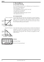
Page 4: ... Anzeigewert Bei einem linearen Verhalten müssen zwei Mess inP bzw Anzeigewerte dSP definiert werden Um die be ste Präzision zu erreichen sollten diese 2 Punkte an beiden Enden des Anzeigebereiches gewählt werden Anzeige wert 2 Anzeige wert 1 Messwert 1 Messwert 2 Negative Steigung Die Koordinaten dieser zwei Punkte können direkt über die Tastatur eingegeben werden SCAL Tastatur Modus oder die ans...

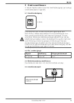
Page 5: ...ensor Anschlussleitungen abzuschirmen und die Abschirmung einseitig zu erden Beidseitige Erdung wird empfohlen bei HF Störung und falls bei grösseren Entfernungen Potential Ausgleichsleitungen installiert sind Die Sensor Anschlussleitungen sollen nicht im gleichen Kabelstrang mit der Netzversorgung und den Ausgangs Kontaktleitungen geführt werden 3 2 Ein und Ausgänge Signal Auflösung Eingangswider...

Page 6: ... blinkt Taste Dient zum inkrementieren hochzählen der angewählte Dekade Programmiervorgang 1 Taste drücken Pro wird angezeigt für Einstieg in die Programmierung Nach wiederholtem Tastendruck erscheint die erste Programmierzeile dSP Anzeige Skalierungsmodus 2 Die benötigten Programmierzeilen mittels der drei Tasten und parametrieren 3 Nach der letzten Programmierzeile werden durch Drücken der Taste...

Page 7: ...uss dieser Wert über die Tastatur eingegeben werden Im Teach Modus wird der Wert des anstehenden Analogsignals übernommen Anzeigewert zum zweiten Messwert Dieser Wert muss über die Tastatur eingegeben und dem zweiten Messwert zugeordnet werden Zulässiger Bereich von 1999 bis 9999 4 2 Programmierung sperren Der Zutritt zur Programmierzeile Programmierung sperren erfolgt am Ende der Anzeigenkonfigur...

Page 8: ... linearisierbar Parameter Dezimalpunkt Datenspeicherung 10 Jahre im EEPROM Auslegung Schutzklasse II DIN EN 61010 1 Überspannungskategorie II Verschmutzungsgrad 2 Störaussendung DIN EN 61000 6 3 Störfestigkeit DIN EN 61000 6 2 Technische Daten mechanisch Umgebungstemperatur 10 60 C Lagertemperatur 25 85 C Relative Luftfeuchte 95 nicht betauend Anschluss Federkraftklemme steckbar Aderquerschnitt 1 ...

Page 9: ...PA210 www baumer com 9 5 1 Abmessungen PA210 ohne Spannrahmen PA210 Spannrahmenmontage 6 Bestellbezeichnung PA210 009AX01 ...

Page 10: ...PA210 10 www baumer com ...

Page 11: ...ts Page General Safety instructions 12 Description 14 System description 14 Display range 14 Connecting 15 Terminal assignment 15 Inputs and outputs 15 Voltage supply connection 15 Wiring examples 15 Operating mode Programming mode 16 Display configuration 17 Programming lock 17 Technical data 18 Dimensions 19 Part number 19 ...

Page 12: ...rate and in safe condition To keep the units in this condition it is necessary that the units be installed and operated properly in a safety and hazard conscious manner under observance of this operating manual and in particular of these safety precautions Make sure that the personnel has read and understood the operating manual and in particular the Safety Instructions chapter In addition to the ...

Page 13: ...life threatening danger health risks or a danger of property or environmental damage could result then appropriate safety precautions must be taken Tampering with the units can have a negative affect on their opera ting safety resulting in dangers Do not make repairs on the units Return defective units to the ma nufacturer Installation commissioning In case of changes including in the operating be...

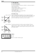
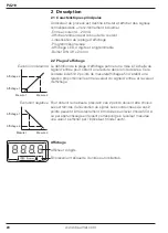
Page 14: ...al and displayed value Linear behavior requires defining two measured values inP respectively displayed values dSP Both limits should be at the end of the display area to ensure maximum precision Displayed value 2 Displayed value 1 Measured value 1 Measured value 2 Linear decrease There are two options to enter the value coordinates Either by keypad in SCAL mode or using the teach in feature teach...

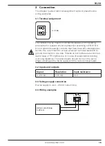
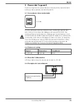
Page 15: ...nassigned ex factory We recommend to screen all sensor terminal leads and to ground the shield on one side Shields on both sides are recommen ded in case of RF interference or in case of equipotential bonding over long distances The sensor leads should not be in the same phase winding as the mains supply and the output contact leads 3 2 Inputs and outputs Signal Resolution Input resistance 4 20 mA...

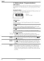
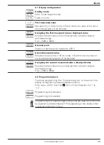
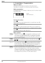
Page 16: ... is flashing Key For incrementing of selected decades Programming 1 Press display will switch to Pro which means access to programming level Another press will make the display skip to first programming line dSP option input signal 2 Proceed with line parameterization using keys and 3 Pressing key after the last programming line will automatically save the parameters which is briefly signaled by S...

Page 17: ...es manual entry in SCAL mode In Teach mode the value of the provided analog signal will be adopted Assigning the second measured value a displayed value Requires manual value entry and assignment using the keypad Admissible range from 1999 to 9999 4 2 Programming lock To access programming line Programming lock at the end of the display configuration please proceed as follows Enter value dSP2 and ...

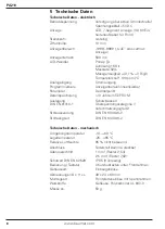
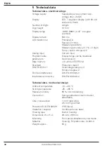
Page 18: ...ised parameters Decimal point Data memory 10 Jahre in EEPROM Standard Protection class II DIN EN 61010 1 Overvoltage category II Pollution degree 2 Emitted interference DIN EN 61000 6 3 Interference immunity DIN EN 61000 6 2 Technical data mechanical design Ambient temperature 10 60 C Storing temperature 25 85 C Relative humidity 95 non condensing Connection Spring loaded terminal connector detach...

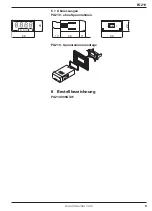
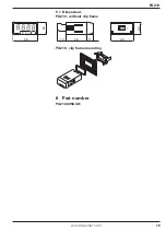
Page 19: ...PA210 www baumer com 19 5 1 Dimensions PA210 without clip frame PA210 clip frame mounting 6 Part number PA210 009AX01 ...

Page 20: ...PA210 20 www baumer com ...

Page 21: ...ription 24 Caractéristiques principales 24 Plage d affichage 24 Raccorder l appareil 25 Raccordement des connecteurs 25 Entrées sorties 25 Alimentation 25 Exemples de raccordements 25 Mode consultation et programmation 26 Configuration de l affichage 27 Verrouillage de la programmation 27 Caractéristiques techniques 28 Dimensions 29 Références de commande 29 ...

Page 22: ...ueur L appareil a quitté l usine de production prêt à fonctionner et en parfait état technique vis à vis de la sécurité Afin de conserver cet état il est indispensable d installer et d utiliser l appareil conformément aux prescriptions en étant informé sur les règles de sécurité et les risques en respectant ce guide utilisateur et particulièrement les consignes de sécurité qu il contient Assurez v...

Page 23: ...entaux alors il faut prendre des mesures de sécurité correspondantes Des interventions dans l appareil peuvent avoir un effet négatif sur la sécurité de fonctionnement et par conséquent être dangereuses N effectuez aucune réparation sur l appareil Retournez l appareil dé fectueux au constructeur Installation Mise en service Suite à des modifications ou changement de comportement qui in fluencent l...

Page 24: ...rée pour obtenir une lecture dans l unité désirée Cela consiste à définir 2 points de mesure affichage afin d établir une relation proportionnelle entre la valeur du signal d entrée et la valeur d affichage Affichage 2 Affichage 1 Mesure 1 Mesure 2 Evolution négative Pour obtenir la meilleure précision ces 2 points doivent être choisis aux extrémités de l évolution du signal Les coordonnées de ces...

Page 25: ...ées par le constructeur Il est recommandé de blinder toutes les lignes de capteurs ou entrées de commande et de relier le blindage à la terre d un coté Le raccorde ment du blindage aux deux extrémités est recommandé en milieu perturbé par des signaux HF ou pour des grandes longueurs de câbles à condition qu il existe une liaison équipotentielle 3 2 Entrées et sorties Signal Résolution Impédance 4 ...

Page 26: ...ionné Mode opératoire 1 Appuyer sur la touche le message Pro s affiche pour confir mer l entrée en mode programmation En appuyant à nouveau sur la touche apparaît la première ligne de programmation dSP Choix du signal d entrée 2 Programmer les différentes lignes à l aide des trois touches et 3 Par un appui sur la touche après la programmation des diffé rentes lignes de configuration l appareil mém...

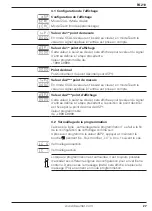
Page 27: ...iqué à l entrée est prise en compte Valeur du 2ème point d affichage Cette valeur à saisir au clavier sera affichée pour la valeur du signal d entrée définie à l étape précédente la position du point décimal est fixée par le point décimal de dSP1 Valeur programmable de 1999 à 9999 4 2 Verrouillage de la programmation L accès à la ligne verrouillage de la programmation se fait à la fin de la config...

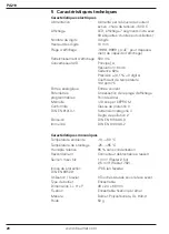
Page 28: ... courant Paramètres Linéarisation de la plage d affichage programmables Point décimal Mémoire 10 ans par EEPROM Conformité Classe de protectio II DIN EN 61010 1 Surtension catégorie II Degré de pollution 2 Emission DIN EN 61000 6 3 Immunité DIN EN 61000 6 2 Caractéristiques mécaniques Température ambiante 10 60 C Température de stockage 25 85 C Humidité relative 95 sans condensation Raccordement C...

Page 29: ...PA210 www baumer com 29 5 1 Dimensions PA210 Sans étrier PA210 Montage avec étrier 6 Références de commande PA210 009AX01 ...

Reviews: