background image

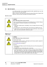
Spare parts

Operation manual 

b maXX


BM4100 (NWR)

Document no.: 5.04052.09

Baumüller Nürnberg GmbH

10

of 142

1.7

1.7

Spare parts

Procure spare parts through an authorized dealer or directly from the manufacturer. 

See also 

Z

Accessories and Spare Parts

– 

from page 111.

1.8

Guarantee provisions

The guarantee provisions are stated in a separate document of the sales documents.

The devices described herein may only be operated in accordance with the stipulated 
methods, procedures and conditions. Anything else not presented here, including the op-
eration of devices in mounted positions, is not permitted and must be cleared with the 
plant on a case-by-case basis. If the devices are operated in any other manner than as 
described within these instruction handbook, then all guarantee and warranty rights are 
rendered null and void.

1.9

Customer service

Our customer service is available to provide you with technical information.

Info on the responsible contact persons is available at all times via telephone, fax, mail or 
the Internet.

1.10 Terms used

The term „device“ or the item designation BM4XXX are also used in this documentation 
for this Baumüller product. A list of the abbreviations used can be found in 

Z

Appendix A 

- Abbreviations

– 

from page 133.

1.11 List of other applicable documents

Parameter hand-
book

WARNING!

False or flawed spare parts can lead to damage, malfunction or complete fail-
ure, thus endangering safety.

Therefore:

m

Only use original spare parts of the manufacturer.

Doc No.

Part No. 
German

Part No. 

English

Parameter manual basic unit b maXX b maXX 4100 mains inverter 

5.04054

392423

392424

Summary of Contents for b maXX 4100 Series

Page 1: ...tion manual Please read these operating instructions before beginning Language English Translation Document No 5 04052 09 Part No 392407 Status 21 Feb 2014 b maXX 4100 Active mains inverter NWR E 5 04052 09 ...

Page 2: ...ents so that we can take them into account and include them when transitioning from the advance information to the final infor mation as reviewed by Baumüller The conditions stipulated in the following section under Obligatory are invalid in case of ad vance information Obligatory These Operation manual are a part of the equipment machine These Operation manual must be available to the operator at...

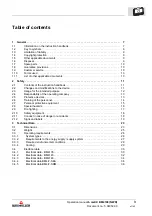
Page 3: ...r the intended purpose 12 2 4 Responsibility of the operating company 13 2 5 Protective devices 13 2 6 Training of the personnel 14 2 7 Personal protective equipment 15 2 8 Special hazards 16 2 9 Fire fighting 17 2 10 Safety equipment 18 2 11 Conduct in case of danger or accidents 18 2 12 Signs and labels 19 3 Technical Data 23 3 1 Dimensions 23 3 2 Weight 25 3 3 Operating requirements 26 3 3 1 Sy...

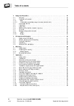
Page 4: ...6 2 Preparing for mounting 52 6 2 1 Drilling patterns 53 6 3 Mounting instructions 55 7 Installation 59 7 1 Safety notes 59 7 2 Voltage test 61 7 3 Demands on the power supply 62 7 4 Requirements to the connecting cables 62 7 5 Protection of the device and the cable 62 7 6 PE connection and RCD compatibility 63 7 7 Installation requirements with regard to EMC 63 7 8 Mains filter and surge protecti...

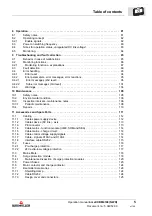
Page 5: ...5 10 2 Environmental condition 106 10 3 Inspection intervals maintenance notes 106 10 3 1 Periodic maintenance 108 10 4 Repairs 110 11 Accessories and Spare Parts 111 11 1 Cabling 112 11 1 1 Cables power supply device 112 11 1 2 Cables device DC link axis 113 11 1 3 PE connector 113 11 1 4 Cable mains function module UME SRM and SEA 114 11 1 5 Cable mains charge circuit 114 11 1 6 Cable control vo...

Page 6: ...uirements to the executing personnel 128 12 3 Shutdown 128 12 4 Demounting 128 12 5 Storage conditions 129 12 6 Recommissioning 130 13 Disposal 131 13 1 Safety notes 131 13 2 Disposal facilities authorities 132 Appenidx A Abbreviations 133 Appenidx B Declaration of Conformity 135 B 1 Declaration of conformity 135 Table of figures 137 Index 139 Overview of Revisions 141 ...

Page 7: ...d safety notes and procedural in structions Additionally the valid accident prevention regulations and general safety regulations ap plicable to the scope of application the device must be complied with Read the instruction handbook particularly the safety notes chapter completely before beginning any work on the device The instruction handbook is part of the product and must be kept accessible to...

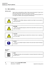
Page 8: ...idents personal injury and material damage Recommen dations DANGER points out an immediately dangerous situation that will lead to severe injuries or death if not avoided WARNING points out a potentially dangerous situation that could lead to severe injuries or death if not avoided CAUTION points out a potentially dangerous situation that could lead to minor or slight inju ries if not avoided NOTI...

Page 9: ...nt protection etc The person who carried out the mounting or installation is liable for any damage incurred when assembling or connecting the device 1 4 Copyright protection The instruction handbook must be treated confidentially It is to be used exclusively by personnel who work with the device The consignment of the instruction handbook to third persons without the written permission of the manu...

Page 10: ...nner than as described within these instruction handbook then all guarantee and warranty rights are rendered null and void 1 9 Customer service Our customer service is available to provide you with technical information Info on the responsible contact persons is available at all times via telephone fax mail or the Internet 1 10 Terms used The term device or the item designation BM4XXX are also use...

Page 11: ...s tasked with performing work on or with the device must have read and understood the instruction handbook before working with the device This also ap plies if the person involved with this kind of device or a similar one or has been trained by the manufacturer 2 2 Changes and modifications to the device In order to prevent hazards and to ensure optimum performance no changes additions or modifica...

Page 12: ... work with on this device m When configuring ensure that the device is always operated within its specifica tions m Mount the device on a wall that can sufficiently bear the load m The device must always be operated within a control cabinet m Ensure that the power supply complies with the stipulated specifications m The device may only be operated in a technically flawless condition m Only operate...

Page 13: ...tion handbook must be kept accessible to personnel working with the de vice at all times in the immediate vicinity of the device m The specifications of the instruction handbook must be adhered to completely and without exception m The device may only be operated in a technically faultless and operationally safe con dition 2 5 Protective devices The devices BM4135 and BM4145 meet the international...

Page 14: ...med by qualified personnel m Qualified personnel n Electrical engineers authorized by Baumüller Nürnberg GmbH and qualified electri cians of the customer or a third party who have learned to install and maintain Baumüller drive systems and are authorized to ground and identify electrical power circuits and devices in accordance with the safety engineering standards of the com pany n Qualified pers...

Page 15: ...ust be observed Wear for special work Protective work clothing should be snug fitting work clothes with low tearing resistance narrow sleeves and with no extending parts It serves to primarily protect against No rings or chains should be worn Hard hat to protect against falling down and flying around objects Safety shoes to protect against heavy objects falling down Protective gloves to protect ha...

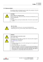
Page 16: ...low work on the electrical system to be performed by qualified personnel m Switch off the current when any kind of work is being performed on the electrical system and ensure safety before switching on again DANGER Risk of fatal injury from electrical current Stored electric charge Discharge time of the rack system discharge time of the device with the longest DC link discharge time in the rack sy...

Page 17: ...tion m Do not open any covering during operation m The amount of residual mechanical energy depends on the application Powered components still turn move for a certain length of time even after the power supply has been switched off Ensure that adequate safety measures are taken DANGER Risk of fatal injury from electrical current There is a risk of electric shock if an electrically conductive fire...

Page 18: ...e device immediately with an EMERGENCY Stop m Initiate first aid measures m Evacuate persons from the danger zone m Notify the responsible persons at the scene of operations m Alarm medical personnel and or the fire department m Keep access routes clear for rescue vehicles WARNING Risk of fatal injury due to non functional safety equipment Safety equipment provides for the highest level of safety ...

Page 19: ...ouch working materials marked correspondingly DANGER Risk of fatal injury from electrical current Stored electric charge Discharge time of the rack system discharge time of the device with the longest DC link discharge time in the rack system See ZElectrical data ab Seite 30 Therefore m Do not touch before taking into account the discharge time of the capacitors and electrically live parts m Heed ...

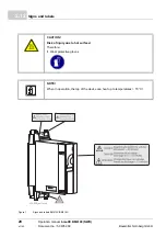
Page 20: ...ocument no 5 04052 09 Baumüller Nürnberg GmbH 20 of 142 2 12 Figure 1 Signs and labels BM413X BM414X CAUTION Risk of injury due to hot surface Therefore m Wear protective gloves NOTE When in operation the top of the device can heat up to temperatures 70 C ...

Page 21: ...Safety Operation manual b maXX BM4100 NWR Document no 5 04052 09 21 of 142 2 Figure 2 Signs and labels BM416X ...

Page 22: ...ls Operation manual b maXX BM4100 NWR Document no 5 04052 09 Baumüller Nürnberg GmbH 22 of 142 2 12 On the type plate label you will find besides others the type key of the device Figure 3 Position of type key label ...

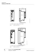
Page 23: ...owing dimension drawings show the main dimensions of the devices By means of the dimension drawings the space requirements within the control cabinet are deter mined The dimension drawings in ZDrilling patterns from page 53 must be used in or der to do the required drilling segments NOTE All dimensions in mm ...

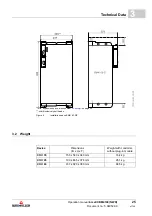
Page 24: ...WR Document no 5 04052 09 Baumüller Nürnberg GmbH 24 of 142 3 1 min expansion space also consider ZCooling on page 29 Figure 4 Installation space BM4135 S min expansion space also consider ZCooling on page 29 Figure 5 Installation space BM4145 S ...

Page 25: ...on space also consider ZCooling on page 29 width inclusively bolt heads Figure 6 Installation space BM4163 S Z 3 2 Weight Device Dimensions B x H x T Weight with controller without plug in module BM4135 155 x 540 x 340 mm 16 4 kg BM4145 190 x 665 x 374 mm 26 1 kg BM4163 437 x 920 x 380 mm 68 5 kg ...

Page 26: ...grounded parts PE The cabinet of the electrical installation is grounded The separation is reached by using an isolating transformer or an independent current source generator battery If the low impedance ground fault is adequate an upstream fuse within the TN system or the TT system responds At a high impedance ground fault a fuse does not respond This ground current residual currents can be dang...

Page 27: ...UAC device 3 x 400 V 50 60 Hz Absolute minimum supply voltage device1 2 UAC Absolute maximum supply voltage device1 2 UAC 3 x 207 V 50 60 Hz 3 x 528 V 50 60 Hz Absolute minimum frequency5 Absolute maximum frequency 5 47 Hz 63 Hz Overvoltage category EN 61800 5 1 chapt 4 3 6 III Harmonics power supply voltage EN 61800 3 Kap 5 2 1 Klasse 3 THDU b 10 Unbalanced power supply voltage EN 61000 2 4 Tab 1...

Page 28: ... temperature range 25 C to 55 C Storage climatic class EN 60721 3 1 1 K 4 Operation environment industrial system 1 Operation temperature range min 5 C to max 55 C rated temperature 40 C Operation climatic class EN 60721 3 3 3 K 3 Mounting height 2 absolute altitude up to 2000 m Humidity operation EN 60721 3 3 relative humidity 5 to 85 no condensation and absolute humidity 1 g m3 to 25 g m3 Ionizi...

Page 29: ...herefore can be necessary to use additional fans so that the necessary cooling air requirement is covered If the necessary cooling air requirement of the power heatsink is not provided then the output power of the device has to be reduced KLK cooling air requirement power heatsink KG cooling air requirement internal space of device Cooling air temperature 1 min 0 C to max 55 C rated temperature 40...

Page 30: ... A PWM switching frequency 8 kHz DC link voltage 640 VDC to 760 VDC DC link capacity internal 2000 µF DC link discharging time internal DC link capacity 430 s DC link capacity external permitted max 18 mF Output power DC link 1 6 max 35 kW Peak power DC link 7 52 kW Max peak power time 5 60 s Power factor only inductive 0 9 to 1 0 Switch on frequency v 2 min see ZPower on switching frequency from ...

Page 31: ... 6 The mains current is reduced by at mains voltage of e g 480 VAC and permitted output power DC link instead of 55 AAC the mains current is 45 8 AAC When selecting the connected drives ensure that the output power of the DC link is not exceeded Figure 8 Derating curve output power DC link BM4135 7 This power output is only permitted for short periods of time max 60 s This must be ensured by param...

Page 32: ...55 µF DC link capacity external permitted max 17 mF DC link discharging time internal DC link capacity 70 s Output power DC link 1 6 max 80 kW Peak power DC link 7 104 kW Max peak power time 5 60 s Power factor only inductive 0 9 to 1 0 Switch on frequency v 2 min see ZPower on switching frequency from page 83 Max charging time b 30 s Fast discharge b 5 s Chopper current permitted Î max 100 A Chop...

Page 33: ...t exceeded Figure 10 Derating curve output power DC link BM4145 7 This power output is only permitted for short periods of time max 60 s This must be ensured by parametrization of the connected drives 8 Incl mains chokes 9 Only valid for cooling variant S 10 The cooling air requirement corresponds is at least to that of a free blowing device Free blowing means that the air inlet and the air outlet...

Page 34: ...ernal 6000 µF DC link capacity external permitted max 14 mF DC link discharging time internal DC link capacity 130 s Output power DC link 1 6 max 150 kW Peak power DC link 7 195 kW Max peak power time 5 60 s Power factor only inductive 0 9 to 1 0 Switch on frequency v 2 min see ZPower on switching frequency from page 83 Max charging time b 30 s Fast discharge b 5 s Chopper current permitted Î max ...

Page 35: ... The mains current is reduced by at mains voltage of e g 480 VAC and permitted output power DC link instead of 235 AAC the mains current is 195 8 AAC When selecting the connected drives ensure that the output power of the DC link is not exceeded Figure 12 Derating curve output power DC link BM4163 7 This power output is only permitted for short periods of time max 60 s This must be ensured by para...

Page 36: ...ta BM4 F SEA 3 4 5 Electrical data BM4 F SRM SEA 01 SEA 02 Min supply voltage 110 VAC 10 50 60 Hz 24 VDC 15 Max supply voltage 230 VAC 10 50 60 Hz 24 VDC 20 Max switching current 8 A 8 A SRM 01 SRM 02 Min supply voltage 110 VAC 10 50 60 Hz 24 VDC 15 Max supply voltage 230 VAC 10 50 60 Hz 24 VDC 20 Max switching current 15 mA 10 mA ...

Page 37: ...sist of a power unit with an integrated charging circuit and an integrated slot for the controller cartridge The controller cartridges itself contain besides the firmly installed controller slot F the voltage sensing module slot A the contactor monitoring module slot B the contactor control module slot C and the digital I O module slot D still a few slots which optional can be equipped The rated c...

Page 38: ...Controller unit At reaching a DC link voltage of 500 V UDC when mains voltage is 400 V and the de crease of the charge current to zero the buck converter is switched off the main contactor release is generated and the main contactor is switched on by the function module BM4 F SEA XX to slot C The monitoring signal of the main contactor is transmitted by the function module BM4 F SRM XX to slot B t...

Page 39: ...existing controller unit variant you can retrofit optional plug in modules function modules and option modules The slots differ in size and func tion 1 and 2 rowed A Function modules permanently installed B C D With this plug in module in this slot the controller communicates via a function module bus Option modules can not be inserted into these slots E F Controller module permanently installed 2...

Page 40: ...BM4 O IEI XX incremental encoder emulation BM4 O ETH 01 Ethernet BM4 O ETH 02 Ethernet CANopen Master BM4 O ECT 01 EtherCAT Slave for PLC BM4 O ECT 02 Ethernet EtherCAT master BM4 O ECT 03 Ethernet EtherCAT cluster A B C D X E o o X X F Controller permanently installed G o o o o o o o X X X X X X X H X X X X X X X o o o X o Permanently installed function module at this slot Preferred slot Baumülle...

Page 41: ...not all Baumüller devices The combination with m BM44XX power modules see operation manual Document no 5 12008 Definitely prohibited is the combination with following devices with a common DC link m other BM41XX mains inverter m all BM44XX basic units in particular BM441X and BM447X 4 4 Type plate On the type plate label you will find besides others the type key of the device Figure 15 Position of...

Page 42: ... cabinet 3 to 6 BM4XXX XXX XXXXX XX Current grading output rated current BM4XXX XXX XXXXX XX Cooling type S air cooled with air supply and with air outlet in the control cabinet BM4XXX XXX XXXXX XX Mains type T TN or TT mains BM4XXX XXX XXXXX XX Safety relay 0 no module BM4XXX XXX XXXXX XX Hardware type XXXXX Power unit construction XXXXX Controller unit variants X0XXX Modules in slots A to E plug...

Page 43: ... by an isolated power supply or control trans former rated max 42 4 V peak 10 000 VA m ZFuses from page 116 n BM4135 may also be protected with Type E self protected combination motor con troller sized based on the rated current n Converters may be used with listed fuses or listed circuit breakers DIVQ as overcur rent protection cUL notes Additional only for Canada NOTE This type key is valid only...

Page 44: ...gulated feedback green Pulse enable DC link voltage is regulated orange Power ON the device is ready for use In case the LED lights up orange col ored during operation maybe the pulse enable is missing green with orange colored flashing or orange with short green flashing Memory operation active in the EEPROM if possible do not switch off the device in this phase red adjusted current limit of the ...

Page 45: ...ingle digits thereby accordingly are shown for about 0 8 s interrupted by a short break If there are further errors the other errors are shown according to the same principle The procedure is repeated as soon as all errors have been shown Example Error 165 and 89 are present Display Status Meaning 0 Not ready to operate Initialization phase pulses inhibited 1 Switch on inhibit Pulses inhibited ini...

Page 46: ...Display and operation elements Operation manual b maXX BM4100 NWR Document no 5 04052 09 Baumüller Nürnberg GmbH 46 of 142 4 8 ...

Page 47: ... to 70 C m Vibration shock continuous shock class 2 M 1 as in EN 60721 3 2 NOTICE Damage due to unauthorized transport Transport handled by untrained personnel can lead to a substantial amount of mate rial damage Therefore m The unloading of the packages upon delivery as well as the in house transport should only be done by trained personnel m Contact Baumüller Nürnberg GmbH sales office if necess...

Page 48: ...responsible representative of Baumüller Nürnberg GmbH 5 4 Unpacking After having received the still packaged device h Avoid transport shocks and hard jolts e g when putting an item down If no transport damage is visible h Open the packaging of the device h Verify the delivery scope based on the delivery note File a claim with the responsible Baumüller representative if the delivery is incomplete 5...

Page 49: ...nel Qualified personnel are persons who on account of their occupational training ex perience instruction and knowledge of relevant standards and stipulations accident prevention regulations and operating conditions are authorized by the persons re sponsible for the safety of the facilities to perform the respective activities that are necessary while at the same time recognizing and preventing an...

Page 50: ...e Therefore m Only allow mounting to be performed by employees of the manufacturer or by oth er qualified personnel WARNING Danger of mechanical impact Secure devices against falling down Therefore m Take suitable measures such as supports hoists and assisting personnel to en sure that device cannot fall down m Use appropriate means of transport NOTICE Danger due to electrostatic discharge The con...

Page 51: ...fted with unprotected hands during mounting palms or fingers can be cut If the device falls feet could be injured Figure 16 Danger area near the mechanical mounting Therefore m Ensure that only qualified personnel who are familiar with the safety notes and as sembly instructions mount this device Wear safety gloves Wear safety shoes ...

Page 52: ...contamination Therefore m When performing installation work of any kind it must be ensured that no foreign material e g drill shavings copper strands etc gets into the device as a result m If possible the drilling of the holes should be done before mounting the device and the configuring of the cables should take place outside of the control cabinet If this is not possible the device must be appro...

Page 53: ... space in the control cabinet see ZDimensions from page 23 Tolerance specifications Figure 17 Drilling pattern BM4135 NOTE Consider the minimum clearances for cooling when making the drill holes All dimensions in millimeters mm Further notes see ZDimensions from page 23 and ZCooling from page 29 Drill hole dimensioning 0 2 mm Dimensioning openings 1 0 mm Relative tolerance of discretionary divisio...

Page 54: ...Preparing for mounting Operation manual b maXX BM4100 NWR Document no 5 04052 09 Baumüller Nürnberg GmbH 54 of 142 6 2 Figure 18 Drilling pattern BM4145 Figure 19 Drilling pattern BM4163 ...

Page 55: ...g Each mounting method is shown in a graphic see ZFigure 20 on page 56 to ZFigure 21 on page 57 The screws and washers required for mounting are listed beneath the respective graphic Carry out mounting as follows 1 Provide suitable transport lifting equipment as needed 2 Keep suitable fastening components readily available 3 Mount the device ...

Page 56: ...maXX BM4100 NWR Document no 5 04052 09 Baumüller Nürnberg GmbH 56 of 142 6 3 Figure 20 Mounting instruction BM4135 S and BM4145 S Device BM4135 S BM4145 S A screws 4 x M5 4 x M5 B washers 4 x 5 3 x 10 4 x 5 3x15 c mounting space c 5 mm c 5 mm ...

Page 57: ...Mounting Operation manual b maXX BM4100 NWR Document no 5 04052 09 57 of 142 6 Figure 21 Mounting instruction BM4163 S Device BM4163 S A screws 4 x M8 B washers 4 x 8 4 x 17 c mounting space c 0 7 mm ...

Page 58: ...Mounting instructions Operation manual b maXX BM4100 NWR Document no 5 04052 09 Baumüller Nürnberg GmbH 58 of 142 6 3 ...

Page 59: ...ormed by employees of the manufacturer or by other qualified personnel Qualified personnel are persons who on account of their occupational training ex perience instruction and knowledge of relevant standards and stipulations accident prevention regulations and operating conditions are authorized by the persons re sponsible for the safety of the facilities to perform the respective activities that...

Page 60: ...operty Therefore m Only personnel from manufacturer or qualified personnel operate while installation and initial commissioning DANGER Risk of fatal injury from electrical current Inevitably when operating this electrical device certain parts of it are energized with hazardous voltage Therefore m Pay heed to areas on the device that could be dangerous during the electrical in stallation m Pay heed...

Page 61: ... to the DC link the DC link discharge can take a much longer time In this case the necessary waiting period must be deter mined or a measurement made as to whether the equipment is de energized This discharge time must be posted together with an IEC 60417 5036 2002 10 warn ing symbol on a clearly visible location of the control cabinet DANGER Risk of fatal injury from electrical current During the...

Page 62: ...he cable must be compliant with IEC EN 60204 1 Section 5 2 Tab 1 h A fixed connection for the protective ground conductor is mandatorily specified for op eration of the device h Use copper cable approved for a minimum of 60 C drives 3 x 100 A or 75 C drives 3 x 100 A if comply with UL 508C For further details e g maximum permitted length see ZCabling from page 112 7 5 Protection of the device and ...

Page 63: ...he type B is permitted on the power supply side of the device m Otherwise a different protective measure must be utilized such as separation from the surroundings by means of double or enhanced isolation or separation from the power supply system by means of an isolating transformer for example NOTE The emission of radio frequency interference RFI is to a great extent dependent on the wiring spati...

Page 64: ...h different EMC categories signal cables mains cables only in a 90 angle m Contact external cable screens when executing through hole mounting which sepa rate the different EMC ranges m Connect the shield of the cables of the b maXX devices plane on both ends and highly conductive with earth 7 8 Mains filter and surge protection module The use of the mains filters mentioned in the manual is mandat...

Page 65: ...ve conductor connection is imperatively required 8 connect the fuses F2 9 connect the charging conductor 10 connect the device via the pre charge terminals X11 1 X11 2 and X11 3 at the pre charge contactor 11 connect the 24 V supply via terminals X100 1 2 X100 5 6 in case you consider UL 508 C limit the current to 4 A 12 connect the mains voltage sensing module 13 connect the motor via main contac...

Page 66: ...ices either signal cb or signal cd can be used we recommend signal cb ce Main contactor ON cf Monitoring signal main contactor cg Fan for power unit only for BM4145 upwards ch Ready for main contactor ON ci Mains filter see ZMains filters on page 118 BFO Surge protections module see ZSurge protection module on page 118 BA 1D1 see ZFigure 29 on page 71 and the following L N X36 Connections for fan ...

Page 67: ...Installation Operation manual b maXX BM4100 NWR Document no 5 04052 09 67 of 142 7 Figure 23 Connection diagram ...

Page 68: ...e manager in ProDrive Select control via ProDrive and or via BACI n The main contactor can be switched on or off with the command On and Off m Control via the Digital IO module n Page Drive manager in ProDrive Select control only via pulse enable n Following is set on default Pin 8 output 4 Ready for main contactor ON Pin 1 input 1 Main contactor ON Following connection is recommended the main con...

Page 69: ...charging of the DC link Therefore it has to be consid ered that the switching input is only activated at inhibited controller and a main contactor which is switched off Chopper resistor control Independent of the switching of the input Discharge DC link X100 4 from a DC link volt age greater than 814 V on the chopper resistor is automatically switched on As soon as the DC link voltage falls below ...

Page 70: ...70 of 142 7 17 7 17 Proposal against system reactions An additional HF mains choke see ZFigure 28 can reduce the system reactions if the reaction to switching frequencies on the mains because of defects within the mains sup ply is too high Figure 28 Proposal against system reactions Mains BM4100 1C1 1D1 Mains filter ...

Page 71: ...of the controller unit ZFigure 34 on page 76 shows the connections of the function modules in the slots A to D The electrical connections for the device BM4135 are shown in the following figure at the back back panel at the back back panel Figure 29 Electrical connections for mains DC link upon others for BM4135 1D1 1C1 DC link Ba Ba Chopper resistor for discharge in front cover 1U1 1V1 1W1 Mains ...

Page 72: ...M4145 are shown in the following figure Figure 30 Electrical connections for mains DC link upon others for BM4145 at the back back panel Fan at the back back panel 1D1 1C1 DC link Ba Ba Chopper resistor for discharge in front cover 1U1 1V1 1W1 Mains connections NOTE X11 1 ZKM and X11 2 RCD must be short circuited with a cable adapted for the mains voltage ...

Page 73: ...nections for mains DC link upon others for BM4163 at the back back panel in front cover X36 L X36 N Fan 1D1 1C1 DC link Ba 1C1 Chopper resistor for discharge 1U1 1V1 1W1 Mains connections NOTE The chopper resistor is connected at the device BM4163 between Ba and 1C1 See also ZFigure 23 on page 67 X11 1 ZKM and X11 2 RCD must be short circuited with a cable adapted for the mains voltage ...

Page 74: ... Nürnberg GmbH 74 of 142 7 18 Electrical connections of the controller unit Figure 32 Connection X100 X100 1 24V SELV PELV X100 2 24V SELV PELV X100 3 n c X100 4 Quick discharge SELV PELV X100 5 M24V SELV PELV X100 6 M24V SELV PELV Do not connect X100 3 This is different to BM44XX devices ...

Page 75: ...Current limit reached H4 red Error X4 reserved 6 DTR DSR 7 RTS 8 CTS 9 reserved 1 reserved 2 TxD RS232 3 RxD RS232 4 DTR DSR 5 Ground RS232 H5 display 7 segment display Standard operation Display drive status Error condition Display error number X2 Connection for Baumüller memory module PSI X3 1 BB on no contact SELV PELV X3 2 BB On middle reversing switch SELV PELV X3 3 Reference potential for 4 ...

Page 76: ...4 F SRM 02 slot B B X1 1 Monitoring signal of main contactor SELV PELV B X1 2 M24V SELV PELV BM4 F SEA 01 slot C C X1 1 Coil of main contactor C X1 2 N C X1 PE PE BM4 F SEA 02 slot C C X1 1 Coil of main contactor SELV PELV C X1 2 M24V SELV PELV BM4 F DIO 01 slot D D X1 1 Main contactor ON SELV PELV D X1 2 D X1 3 D X1 4 D X1 5 Ready for pulse enable SELV PELV D X1 6 Power limit reached SELV PELV D ...

Page 77: ... SRM 02 NOTE The maximal switching current of SEA is 8 A NOTE in case you consider UL 508 C limit the current to 4 A do not provide the terminals X100 3 or X100 4 with voltage if the device is not sup plied with voltage via X100 1 2 the signals mains on and chopper resistor are internal digital control signals of the system b maXX They are used at applications with DC link connection The PSI modul...

Page 78: ...wer ZTechnical Data from page 23 4 The cable lug may be 25 mm wide at most The maximum cable diameter is dependent on the cable lug In case the cable lug which you use can safely clamp a stronger cable than 95 mm2 you may also use stronger cables than 95 mm2 5 The cable lug may be 35 mm wide at most The maximum cable diameter is dependent on the cable lug In case the cable lug which you use can sa...

Page 79: ...can do unexpected actions Therefore Connect the PC via an isolated transformer or use a battery operated PC e g lap top notebook without connecting a charger NOTE In case you don t use an optically decoupled interface cable the cable shield has only to be connected to the connector housing at the controller connector The company Baumüller Nürnberg GmbH recommends the usage of optically decou pled ...

Page 80: ... 1 5 2 5 mm2 plug in contact X11 1 to X11 5 H07 to 1000 V see ZPre charge protec tion on page 117 A X1 to C X1 1 Cable Ø Connection technology Load capacity BM4135 BM4145 BM4163 0 75 2 5 mm2 plug in contact X1 1 X1 2 and X1 3 H07 to 1000 V max 1 0 A D X1 Cable Ø Connection technology Load capacity SELV PELV BM4135 BM4145 BM4163 0 75 1 5 mm2 plug in contact X1 5 to X1 10 in case you consider UL 508...

Page 81: ...work ensure that all coverings and protective devices are installed and are functioning properly m The control cabinet in which the device is installed should be protected against contact with electrically live parts Keep all doors of the control cabinet closed during operation NOTICE Environmental conditions that do not meet the requirements Environmental conditions that are non compliant can lea...

Page 82: ...e of an error the service engineer can with the help of Pro Drive determine the error 8 2 1 Enable signals These signals must have a signal level of 24 V DC and must be connected to the termi nals X3 4 and X3 5 ZFigure 23 on page 67 Pulse enable During operation the signal pulse enable must constantly be available so that the device supplies power Additionally the pulse enable has to be generated ...

Page 83: ...DC link voltage from firmware version FW 03 07 upwards The controller is able to block the IGBTs if a mains fault but no mains power failure oc curs The device operates only with free wheeling diodes Therefore the DC link is not regulated The function module DIO generates a signal as soon as the controller unit recognizes a mains fault In order that all power modules reduce the output power This s...

Page 84: ...to an error condi tion an accordant warning message is shown in ProDrive and by the control respectively The most important warning current limit reached the device also shows via the LED H3 see ZCurrent limit H3 on page 44 Error message The controller unit recognizes that the device is not error free this is shown via the LED H4 see ZError H4 on page 44 and via the 7 segment display Furthermore a...

Page 85: ...zed with hazardous voltage Therefore m Pay heed to areas on the device that could be dangerous WARNING Risk of injury due to improper fault correction Therefore m Only qualified personnel may work on this device m Personnel that work with the b maXX device must be trained in the safety regula tions and the handling of the device and be familiar with the correct operation of it In particular reacti...

Page 86: ...oring Phase failure X X IS Mains failure X X IS1 Frequency monitoring Frequency range X X IS Frequency change X X IS Earth fault Fault current to earth X IS Overcurrent Overcurrent of the device X IS DC link DC link overvoltage X IS DC link undervoltage X X IS Ixt threshold Peak current e g not possible X X X IS Temperature heatsink Temperature threshold 1 X X P0018 Temperature shutdown threshold ...

Page 87: ...unction checks the following n If the mains frequency value is within the permissible frequency range If the value is lower or higher the controller generates an error message Frequency range error and an immediate pulse inhibit occurs n If the mains frequency change is too high If the mains frequency change is 5 Hz s the controller generates an error message Frequency change error and immediately...

Page 88: ...emperature of the heatsink m In case the temperature is higher than the warning threshold the controller gives a warning m In case the temperature is too high immediately a pulse inhibit occurs Connection monitoring This monitoring checks if the connections at the mains and at BM4F UME 01 are in phase If the phases are not in phase the controller generates the error message con nection error and a...

Page 89: ...r param eters error messages error reactions from page 95 The displayed error is without ex ception an LEVEL 2 error P0201 P0216 The display of an error code starts therewith that F is displayed for 1 5 s Then the four characters of the error code are displayed The separate characters are displayed for about 0 8 s interrupted by a short break If there are other errors these are displayed in the sa...

Page 90: ...are version of the controller and the ProDrive version is not compatible following message is displayed also see online help ProDrive Figure 38 ProDrive version conflict NOTE The controller software version and the operating software version must be compat ible to use ProDrive with all functions NOTE Please contact Baumüller Nürnberg GmbH or visit our website www baumueller de for download the lat...

Page 91: ...tion manual b maXX BM4100 NWR Document no 5 04052 09 91 of 142 9 Start screen Figure 39 ProDrive start screen Display the error message in ProDrive h Open navigation with click on in front of Management Figure 40 Project navigation in ProDrive ...

Page 92: ...r The newly occurring messages are added to the end of the list when communication is active Figure 41 Drive manager ProDrive NOTE If you are not able to start the motor although the red LED H4 is not lighting up and although the LED H2 is lighting up green check the parameterization of the b maXX 4000 with the parameter list in ProDrive Error possibilities are e g torque limit 0 has been set or n...

Page 93: ...se of the drive are saved chronologically in this error memory A read access to the error memory is done element by element with an index parameter P0258 and a value parameter P0259 The error memory will be deleted completely at error acknowledgment Bit 7 1 in control word For a further description see parameter P0257 in the Parameter Manual Error display If an error appears the according definite...

Page 94: ...erated by the control system or by operating software via input to parameter list Note The drive control must be active see parameter P1001 Communication source for the selected communication source m Via a digital input A digital input of a DIO module can be selected via parameter P0575 digital input for error acknowledgement can be selected for error reset A rising edge on this input re sets the...

Page 95: ...s errors are not shown in ProDrive 7 segment display Bit mapping see description of the parameter P0200 in the parameter manual 2nd level 3rd level Order of the error messages see survey ZFigure 43 on page 95 2nd level error messages are displayed on the 7 segment display in ProDrive LEVEL 1 LEVEL 2 LEVEL 3 SysError 1 ProcessorError OperationError ProprogError ExtendedModuleError PSU_Error AmpErro...

Page 96: ... P0202 Error operating system Error No Meaning Reaction Troubleshooting 0 reserved 1 Watchdog error IS Restart BM4100 NWR 2 Incorrect or unexpected interrupt has occurred IS 3 NMI Interrupt bus error IS 4 to 15 reserved not assigned 0 Error No Meaning Reaction Troubleshooting 16 Boot error IS Restart BM4100 NWR 17 Software error IS 18 Time slot configuration IS 19 Time slot time error IS Restart B...

Page 97: ...operation state not writable adjustable Check operating condition and parameterization 44 Invalid parameter value adjustable Enter with a valid value 45 Communication error ProDrive controller adjustable Establish connection again or set parameter P0290 to 0 46 to 47 reserved not assigned 0 Error No Meaning Reaction Troubleshooting 48 Error in function module A 3rd level error see ZError in functi...

Page 98: ...he BM4 F UME 01 and if they are energized 70 Frequency change IS Assure the compliance with the power supply specifi cations see ZRequirements to the energy supply supply system on page 27 71 Frequency range error IS 72 Error of main contactor IS Check the connections of the main contactor and of the function module BM4 F SEA xx 73 No monitoring signal from the main contactor IS Check the connecti...

Page 99: ...heat sink temperature of the device is 5 C If the error occurs even at a heat sink temperature 5 C pass on the device for repair 87 Safety relay off or defect IS Check safety relay change on request 88 Bridge short circuit IS Restart BM4100 NWR At recurring error messages exchange the controller 89 Up to FW 03 08 power unit not ready to operate From FW 03 09 reserved IS Make sure that the power un...

Page 100: ...9 No boot data set IS The data in the EEPROM are invalid please safe all data records 180 Incompatible software IS 181 There is no data set adjustable 182 Checksum error im PSI module adjustable PSI EEPROM faulty or write faulty 183 PSI is reset adjustable Please save all data records 184 PSI data invalid adjustable The data in the PSI are invalid please save all data sets 185 to 191 reserved not ...

Page 101: ...rite protected 15 Invalid access code 16 Data field is not changeable in its size 17 Word address outside of data field 18 Data field is nonexistent 36 Wrong data checksum 37 No response Error code Meaning Reaction Troubleshooting 0 reserved 1 Module not recognized no reaction Check if you have plugged in the right module at the right position 2 Recognized module not permitted at this posi tion 3 ...

Page 102: ...ble 4114 Wrong parameter No at actual value parameter 3 adjustable 4115 Wrong parameter No at actual value parameter 4 adjustable 4116 Wrong parameter No at actual value parameter 5 adjustable 4117 Wrong parameter No at actual value parameter 6 adjustable 4118 Wrong parameter No at actual value parameter 7 adjustable 4119 Wrong parameter No at actual value parameter 8 adjustable 4120 Wrong paramet...

Page 103: ...ue wrong adjustable Check the value of the transmitted parameter 4156 Error cyclic communication Alive counter conflict adjustable Check if option module and controller are synchro nous 4157 Cmd interface Channel number wrong 0 or 6 adjustable Contact Baumüller Nürnberg GmbH 4158 Cmd interface Selected channel not available adjustable 4159 Cmd interface Internal error wrong pointer adjustable 4160...

Page 104: ... 01 module and are carrying voltage 7 Frequency change Assure the compliance with the specifications see ZRequirements to the energy supply supply system on page 27 8 Frequency range 9 Mains connections Check the connections of BM4 F UME 01 module and of the mains terminals 10 Pre charge is running Wait until the pre charging has been completed check if the mains voltage is connected 11 Undervolta...

Page 105: ...current Inevitably when operating this electrical device certain parts of it are energized with hazardous voltage Therefore m Pay heed to areas on the device that could be dangerous during the electrical in stallation m Pay heed to areas on the device that could still be electrically energized after op eration Figure 44 Hazard areas during electrical installation ...

Page 106: ...service life It is recommended to have inspections performed reg ularly by qualified personnel Daily inspection Basic check points as to whether discrepancies have occurred during operation m Does the motor work as desired m Is the operating environment normal m Is the cooling system working normally m If an unusual vibration or noise is noticed during operation m Does the motor overheat during op...

Page 107: ...arge time of the system discharge time of the device with the longest DC link discharge time in the DC link connection Refer to ZElectrical data from page 30 Therefore m Do not touch before taking into account the discharge time of the capacitors and electrically live parts m Heed corresponding notes on the equipment m If additional capacitors are connected to the DC link the DC link discharge can...

Page 108: ...ly Annu ally Check the voltage of the power supply system and the control circuits Measurement and comparison with standard values O Check points Methods and criteria Inspection intervals Daily Semi annu ally Annu ally Are there any abnormal noises or vibrations Visual and audio check O Are there any loose screws Tighten the screws O Are there any bent or damaged parts Visual inspection O Have the...

Page 109: ...d criteria Inspection intervals Daily Semi annu ally Annu ally Are there any abnormal vibrations or noticeable odors Visual inspection audio check and odor check O Check points Methods and criteria Inspection intervals Daily Semi annu ally Annu ally Are there any loose screws Visual and audio check Tighten screws if necessary O Do the switches function correctly Visual inspection O Check points Me...

Page 110: ...emberg Germany Tel 49 9 11 54 32 0 Fax 49 9 11 54 32 1 30 Mail mail baumueller de Internet www baumueller de Check points Methods and criteria Inspection intervals Daily Semi annu ally Annu ally Are there any abnormal noises or vibrations Visual and audio check O Are there any loose screws Tighten the screws O Check points Methods and criteria Inspection intervals Daily Semi annu ally Annu ally Ar...

Page 111: ...X BM4100 NWR Document no 5 04052 09 11ACCESSORIES AND SPARE PARTS Accessories spare parts for devices of the b maXX series are listed in this appendix Product management is happy to handle any queries and suggestions on accessory parts ...

Page 112: ...installation you must use UL certified circuit cables 2 Device Cross section 1 Connection to the device BM4135 4 x 6 mm2 to 4 x 16 mm2 flexible cable with wire end ferrule screw terminal BM4145 4 x 16 mm2 to 4 x 50 mm2 BM4163 4 x 25 mm2 to 4 x 150 mm2 cable lug max width 35 mm current bar 2 Connection lugs current bars Position see ZFigure 31 on page 73 Screw maximum two cable lugs to the current ...

Page 113: ...cable lugs according to DIN46230 must be used 3 11 1 3 PE connector m Cross section min 10 mm copper or 16 mm aluminium conductor m Both connection terminals for the PE connector have an identical cross section like the original PE connector Device Cross section 1 Connection to the device BM4135 2 x 6 mm2 to 2 x 16 mm2 male cable lug according DIN46230 2 screw terminal BM4145 2 x 16 mm2 to 2 x 50 ...

Page 114: ...er cables with this maximum length and when using a Baumüller mains filter you can assume that the compliance with the EMC regulation is fulfilled 11 1 6 Cable control voltage supply signals 1 The installing of the cables is user defined 2 The length of the cable has no influence on the compliance to the EMC regulation 11 1 7 Cable signals X100 3 and X100 4 1 Cables longer than 3 m must be screene...

Page 115: ...is available as a spare part see ZCable RS232 on page 124 1 Use the following materials m Cable LIYCY 6x2x0 14 mm2 m Sub D connectors 9 pole female cabinet plastics metallized m Sub D connector 9 pole male cabinet plastics metallized 2 connect the cable shield with the cabinet and with the shield of the Sub D connector Figure 45 Interface cable RS 232 ...

Page 116: ...n the DC link Carry out the fusing in accordance with EN 60204 1 Electrical Equipment of Machines Dimension the cable fuse based on the cross section of the power supply cable used and in accordance with the respective applicable national standards and local regulations The current carrying capacity of the cables is specified in Table 5 of EN 60204 1 For your application the corresponding value mu...

Page 117: ...e terminal block for cartridge fuse insert made by Phoenix Contact Part no 3004100 part name UK 5 HESI 11 2 2 24V extra low voltage protection In case you refer to UL 508 C Assure that all marked e l v connections 24 V at the device have a maximum voltage of 30 VDC Additionally these connections must be protected with fuses which are in ac cordance with UL 248 with a triggering current of maximum ...

Page 118: ... Surge protection module A surge protection module BFO 3 550 00 article number 386058 is mandatory in every application The module must be connected as follows Figure 46 Connection surge protection module Device Input rated current Input peak current Schaffner filter www schaffner com BM4135 55 A 82 5 A FN 3120H 80 35 BM4145 125 A 162 5 A FN 3120H 150 40 BM4163 300 A 340 A FN 3100 300 99 bis 2013 ...

Page 119: ...rotection against over voltage from the mains as well as against overvoltage in case of mains failure in combi nation with the required mains filter and the required commutating choke NOTE If the surge protection module BFO 3 550 00X is not used or not connected accor ding connection diagram any kind of claim to warranty will expire for the b maXX 4100 active mains converter NOTE The surge protect...

Page 120: ...cabinet that all devices in the control cabinet are off circuit and are safe against re starting Await the discharge of the DC link before you install the safety relay The capacitors which are used in the device are 10 min after interruption of the supply voltage au tomatically discharge so far that the connections can be demounted without danger If you have additional capacitors connected to the ...

Page 121: ...pection Surge protection module without damage m no staining The surge protection module can be assembled and installed again Surge protection module damaged phase to phase voltage 550 V over a longer period m Varistors stained m Varistors black m Varistors exploded A new surge protection module must be installed ...

Page 122: ...l devices in the control cabinet are off circuit and are safe against re starting Await the discharge of the DC link before you install the safety relay The capacitors which are used in the device are 10 min after interruption of the supply voltage au tomatically discharge so far that the connections can be demounted without danger If you have additional capacitors connected to the DC link the DC ...

Page 123: ...mag UL listed Device Name Inductance Part number BM4135 BL 3 060 000 1 0 mH 388168 BM4145 BL 3 130 000 0 48 mH 388741 BM4163 BL 3 240 000 0 36 mH 396302 Type A B C D E F G Connection Fixing BM4135 260 300 306 110 140 9x13 8 5 bar with hole M8 M8 BM4145 300 360 330 110 140 9x13 8 5 bar with hole M8 M8 BM4163 430 480 420 160 220 13x26 11 bar with hole M10 M12 Device Name Inductance Part number BM413...

Page 124: ...or 130 A 480 V 6 A 400 480 V BM4163 250 A 400 V or 250 A 480 V 6 A 400 480 V Type Part No Width 11 mm for cable diameter up to 8 mm 00312171 Width 19 mm for cable diameter 7 mm to 16 mm 00397366 Width 27 mm for cable diameter 6 mm to 24 mm 00397375 Width 43 mm for cable diameter 22 mm to 40 mm 00397376 NOTE In case you don t use an optically decoupled interface cable the cable shield has only to b...

Page 125: ...62 1714317 X X X 409624 Connector X3 Phönix FK MCP 1 5 6 ST 3 81 1851083 X X X 354874 Connector X100 Wieland 8513 BFK 25 630 3653 0 X X X 354810 Connector A X1 Phönix GMSTB 2 5HCV 4 ST 7 62 1714294 X X X 409625 Connector B X1 C X1 for version 01 Phönix FRONT GMSTB 2 5 3 ST 7 62 1806122 X X X 385623 Connector B X1 C X1 vor version 02 Phönix FRONT GMSTB 2 5 2 ST 7 62 1766990 X X X 396131 Connector D...

Page 126: ...Baumüller accessories Operation manual b maXX BM4100 NWR Document no 5 04052 09 Baumüller Nürnberg GmbH 126 of 142 11 7 ...

Page 127: ...ectrically live parts before taking into account the discharge time of the capacitors m Assure that all electric connections are current free and are safe against switch on m Before working check at the electrical connections with suitable measuring devic es that the connections are off circuit m Remove the connections not until the safe isolation from supply has been checked m If additional capac...

Page 128: ...arliest 10 minutes after switching off 3 demount the connections and protect the connections according to the safety instruc tions 4 document the shut down setting 12 4 Demounting The demounting assumes a completed documented setting out of operation 1 secure the device against falling off out 2 loosen all mechanical connections 3 lift the device out of the control cabinet 4 store the device in a ...

Page 129: ...correct storage can damage destroy the device Therefore Assure that the environmental conditions are kept during the entire period of storage m Climatic category 1K4 m Temperature range 25 C to 55 C CAUTION Recommissioning without forming of the capacitors From six months storage period on the capacitors are destroyed during commission ing if they are not formed beforehand m Reform the DC link cap...

Page 130: ...nths storage period on the capacitors are destroyed during commission ing if they are not formed beforehand m Reform the DC link capacitors n by supplying the device ready to operate for at least one hour with supply voltage n but do not transmit a pulse enable during this time m Consider that it is imperative to connect the accordingly prescribed line commu tating reactor for this forming procedu...

Page 131: ...me of the device with the longest DC link discharge time in the DC link connection Refer to ZElectrical data from page 30 Therefore m Do not touch before taking into account the discharge time of the capacitors and electrically live parts m Heed corresponding notes on the equipment m If additional capacitors are connected to the DC link the DC link discharge can take a much longer time In this cas...

Page 132: ...lations m Take heed of any special local regulations If you are unable to directly ensure safe disposal yourself commission a suitable disposal contractor m In the event of a fire hazardous substances could possibly be generated or re leased m Do not expose electronic components to high temperatures m Beryllium oxide is used as inner insulation for example for various power semicon ductors The ber...

Page 133: ...nction module incremental en coder ESD Electrostatic discharge EXT ext external FI Residual current HS Main contactor HSE Main contactor on HSF Main contactor enable Î Peak current curve shape not de fined IAC Effective value alternating current IAist Armature current actual value IDC Effective value direct current Ieff Effective value alternating current IF Pulse enable ID No Identification numbe...

Page 134: ...SYNC Synchronization message TM Motor temperature sensor U Voltage Û Peak voltage UA Armature voltage UAC Effective value alternating voltage UDC Effective value direct current volt age Ueff Effective value alternating voltage UZK DC link voltage V Volt VDE Association for Electrical Elec tronic Information Technologies ZK DC link ...

Page 135: ...135 of 142 Operation manual b maXX BM4100 NWR Document no 5 04052 09 APPENDIX B DECLARATION OF CONFORMITY B 1 Declaration of conformity ...

Page 136: ... XX manufactured since 11 2007 are developed designed and manufactured in accordance with the EMC Directive 2004 108 EC and the Low Voltage Directive 2006 95 EC Applied harmonized standards Attention should be paid to the safety instructions in the manual Nuremberg 28 11 2007 Location Date Subject to change of this declaration of EC conformity without notice Actual valid edition on request Standar...

Page 137: ...uring electrical installation 60 Connection diagram 67 Proposal control power On Off 68 Connection main contactor control via Digital IO module 68 Proposal controlling pulse enable 69 Recommended chopper resistor control 69 Proposal against system reactions 70 Electrical connections for mains DC link upon others for BM4135 71 Electrical connections for mains DC link upon others for BM4145 72 Elect...

Page 138: ...Operation manual b maXX BM4100 NWR Document no 5 04052 09 Baumüller Nürnberg GmbH 138 of 142 Table of figures ...

Page 139: ... 38 Cooling 29 Cooling type 42 Current grading 42 Current limit reached 44 Customer service 10 D Danger 8 Danger situation 18 DC link 120 122 DC link discharge time 61 107 131 DC link voltage 38 Declaration of conformity 135 Demounting 128 Design cover 125 Device generation 42 43 Discharge 120 122 Display elements 44 Disposal 9 131 Drive management 92 E Edges sharp 51 128 Electrical current danger...

Page 140: ...actor 38 Power unit 37 ProDrive 92 Protective conductor Connection 71 Protective equipment 15 Protective eye wear 15 Protective gloves 15 Protective work clothing 15 Pulse enable 44 82 Q Quick stop 82 R Rated current 37 Recommissioning 130 Repairs 110 Required environmental conditions 28 Residual energy danger from 16 61 Rows 38 S Safety equipment 18 Safety fuses 116 Safety shoes 15 Screwing UL 80...

Page 141: ...Operation manual b maXX BM4100 NWR Document no 5 04052 09 141 of 142 Overview of Revisions Overview of Revisions Version Status Changes 5 04052 09 27 Feb 2014 new layout new BFO module ...

Page 142: ...Operation manual b maXX BM4100 NWR Document no 5 04052 09 Baumüller Nürnberg GmbH 142 of 142 Notes ...

Page 143: ......

Page 144: ... our permanent revision service Please notice that specifications data information are current values according to the printing date These statements are not legally binding according to the measurement computation and calculations Before you make any information given in this manual to the basis of your own calculations and or applications please make sure that you have the latest edition of the ...

Reviews: