Installation
Operation manual
b maXX
BM4100 (NWR)
Document no.: 5.04052.09
65
7
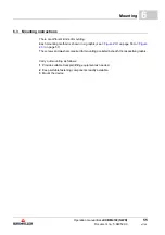
7.11 Installation procedure
h
Lay all cables EMC-compatible.
h
Connect cables (see
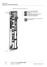
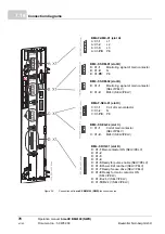
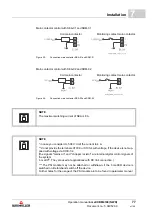
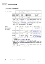
Connection diagram with SEA-01 / SRM-01
(Observe the torques!)
The following steps must be carried out at installation:
1
connect the fuses (F1).
(in case you consider UL 508 C: use UL-listed fuses, see chapter
page 116.)
2
connect the mains filter
3
connect the main contactor to the mains filter.
4
connect the surge-protection module.
5
connect the choke (D1) to the main contactor output.
6
connect the device via the mains input terminals 1U1, 1V1 and 1W1 to the mains
choke output.
7
close the protective conductor at the terminal PE (a permanent protective conductor
connection is imperatively required).
8
connect the fuses (F2).
9
connect the charging conductor.
10
connect the device via the pre-charge terminals X11/1, X11/2 and X11/3 at the pre-
charge contactor.
11
connect the 24 V supply via terminals X100-1/2, X100-5/6.
in case you consider UL 508 C: limit the current to 4 A).
12
connect the mains voltage sensing module.
13
connect the motor via main contactor monitoring module.
14
connect the motor main contactor release module 1U1, 1V1, 1W1, PE.
15
connect the digital I/O module.
16
connect the DC link via 1C1 and 1D1.
17
perhaps connect dependent on the application via the terminals Ba+ and Ba-/1C1 a
quick discharging resistor.
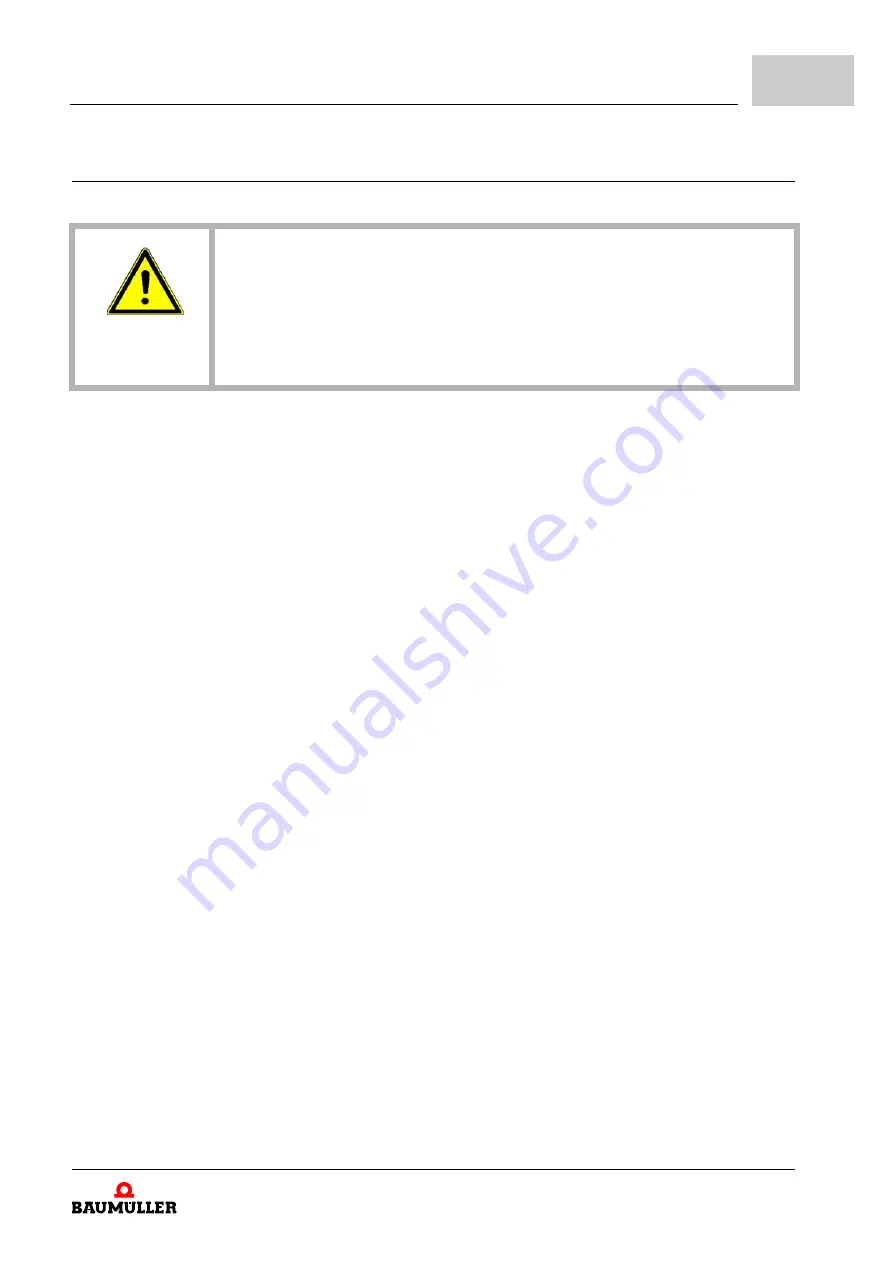
DANGER!
Risk of fatal injury from electrical current!
Electrically live parts are life-threatening.
Therefore:
m
Make certain that the parts to be mounted (e.g. power supply cables) and the
mounting areas are de-energized for the entire duration of mounting the device.
Summary of Contents for b maXX 4100 Series
Page 143: ......

