


Installation
Instruction handbook Mains filters
BFN
Document No.: 5.09010.03
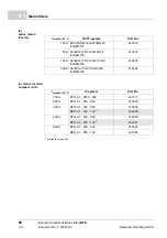
53
7
m
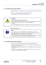
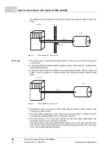
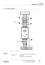
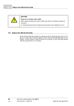
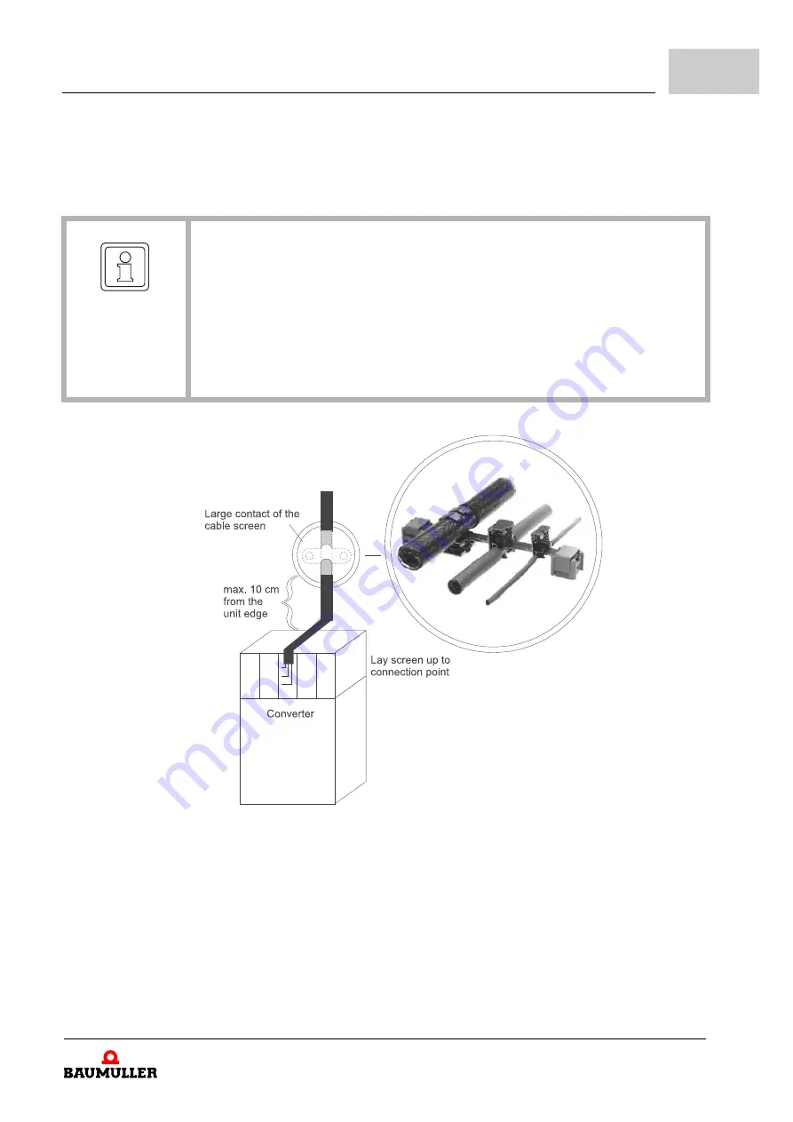
The screen connection must be made with a large surface area and low impedance.
Cable tails with a length of only 3 cm (1 cm wire = 10 nH) reduce the screening effect
with errors in the MHz range up to 30 dB!
Figure 18:
Proposal for a screening connection
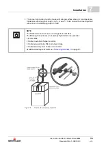
NOTE
The braided screen must have a coverage of at least 85 %.
The following lines possess an especially high interference potential:
m
Motor cable
m
Cable to external chopper resistors
m
Cable between mains filter and power choke
m
Cable between power choke and converter
Summary of Contents for BFN 3-1 Series
Page 71: ......